Skip to content

re-ws.pl

ReverseEngineering WorkStation

  • Home
  • Tutorials
  • Random
  • About

Tag: hardware

LKV373A: porting objdump

Posted on December 30, 2017 - October 17, 2019 by Kamil (aka. v3l0c1r4pt0r)

This article is part of series about reverse-engineering LKV373A HDMI extender. Other parts are available at:

  • Part 1: Firmware image format
  • Part 2: Identifying processor architecture
  • Part 3: Reverse engineering instruction set architecture
  • Part 4: Crafting ELF
  • Part 5: Porting objdump
  • Part 6: State of the reverse engineering
  • Part 7: radare2 plugin for easier reverse engineering of OpenRISC 1000 (or1k)

After part number four, we already have ELF file, storing all the data we found in firmware image, described in a way that should make our analysis easier. Moreover, we have ability to define new symbols inside our ELF file. The next step is to add support for our custom architecture into objdump and this is what I want to show in this tutorial.

Finding best architecture to copy

If we want to set up new architecture in objdump code, we need to learn interfaces that need to be implemented. It would be easier if we can use some existing code to do so. After some looking into the binutils’ code I learned that what is of special interest are bfd and opcodes libraries. They contain code dedicated to particular architectures. The first one seem to be related to object file handling (which in our case is ELF), so we should not tinker with it too much. Second one is related to disassembling binary programs, so is what we are looking for.

I did some quick examination of source code related to popular architectures and it seems not to be easy to adjust to our needs. Architecture I found to be best suitable for modification is Microblaze. Its source seem to be quite well-written, clean and short. Also from my research of architecture name for LKV373A (part 2, failed by the way) I also remember it is quite similar to the one present in LKV373A, so it is even better decision to use it.

Compiling objdump for target architecture

At first it is useful to learn how to compile objdump, so it will be able to disassemble program written for our target. Microblaze is not really a mainstream architecture, so there aren’t many programs compiled for it available online after typing 'microblaze program elf' into usual search engine. However, I was able to find 2 of them, so I was able to verify that compilation worked. If you can’t find any, I uploaded these to MEGA, so they can serve as test cases. First one is minimal valid file, the other one is quite huge.

Compilation is very easy. The only thing that needs to be done beside usual ./configure && make && make install is adding target option to configure script. So, the script looks as follows:

./configure --target=microblaze-elf

Of course, install step can safely be skipped as well as compilation of other tools, beside objdump. objdump itself seem to be built using make binutils/objdump. However it can’t be build successfully using that shortcut, so whole binutils package must be configured the way, everything not buildable is excluded from the build.

Setting up own architecture

Next step is to add support for our brand new, custom architecture to binutils’ configuration files and copy microblaze sources, so they will simulate our architecture, until we will write our own implementation. Then it should be possible to test objdump again, against our sample microblaze programs and disassembly should still work.

Even without any modification to binutils’ source or configs, it should be possible to configure it for any random architecture. The only constraint is format of the target string: ARCH-OS-FORMAT, where FORMAT is most likely to be elf. So, if we pass lkv373a-unknown-elf as target, it will work. -unknown part is usually skipped and this will not work. If we need it to work, config.sub must be modified. config.sub is used to convert any string, passed to configure into canonical form, so in our case lkv373a-unknown-elf. If it detects, that it is already in canonical form, it does nothing.

Final configure command will be slightly more complex, as we have to disable some parts, that are not of our interest and requires additional effort to work:

./configure --target=lkv373a-unknown-elf --disable-gas --disable-ld --disable-gdb

Although passing something random as target option works on configure stage, it will obviously fail on make stage. What make is doing at first is configuring all the sublibraries. What is of our interest is bfd and opcodes. And the first one fails. So this is the first problem, we need to get rid of.

bfd/config.bfd

The purpose of this file is to set some environment variables depending on target architecture. If it does not know the architecture, it returns error to caller, which is probably bfd’s configure script, called by make. According to documentation in file header, it sets following variables:

  1. targ_defvec – default vector. This links target to list of objects that will provide support for ELF file built for specific architecture (stored in bfd/configure.ac)
  2. targ_selvecs – list of other selected vectors. Useful e.g. when we need support for both 32- and 64-bit ELFs. Not needed here.
  3. targ64_selvecs – 64-bit related stuff. Used when target can be both 32- and 64-bit, meaningless in our case.
  4. targ_archs – name of the symbol storing bfd_arch_info_type structure. It provides description of architecture to support.
  5. targ_cflags – looks like some hack to add extra CFLAGS to compiler. We don’t care.
  6. targ_underscore – not sure what it is, should have no impact on our goals (possible values are yes or no)

To sum up, what we need to do on this step is to define default vector, we will later add to configure.ac and set name of architecture description structure. The structure itself will be defined later. Finally, I ended up with the following patch:

@@ -173,6 +173,7 @@ hppa*)     targ_archs=bfd_hppa_arch ;;
 i[3-7]86)   targ_archs=bfd_i386_arch ;;
 i370)     targ_archs=bfd_i370_arch ;;
 ia16)     targ_archs=bfd_i386_arch ;;
+lkv373a)  targ_archs=bfd_lkv373a_arch ;;
 lm32)           targ_archs=bfd_lm32_arch ;;
 m6811*|m68hc11*) targ_archs="bfd_m68hc11_arch bfd_m68hc12_arch bfd_m9s12x_arch bfd_m9s12xg_arch" ;;
 m6812*|m68hc12*) targ_archs="bfd_m68hc12_arch bfd_m68hc11_arch bfd_m9s12x_arch bfd_m9s12xg_arch" ;;
@@ -924,6 +925,10 @@ case "${targ}" in
     targ_defvec=iq2000_elf32_vec
     ;;

+  lkv373a*-*)
+    targ_defvec=lkv373a_elf32_vec
+    ;;
+
   lm32-*-elf | lm32-*-rtems*)
     targ_defvec=lm32_elf32_vec
     targ_selvecs=lm32_elf32_fdpic_vec

bfd/configure.ac

Now we need to define vector, we just declared to use for lkv373a architecture.

505     k1om_elf64_fbsd_vec)         tb="$tb elf64-x86-64.lo elfxx-x86.lo elf-ifunc.lo elf-nacl.lo elf64.lo $elf"; target_size=64 ;;
506     lkv373a_elf32_vec)           tb="$tb elf32-lkv373a.lo elf32.lo $elf" ;;
507     l1om_elf64_vec)              tb="$tb elf64-x86-64.lo elfxx-x86.lo elf-ifunc.lo elf-nacl.lo elf64.lo $elf"; target_size=64 ;;

Unfortunately, as we did modifications to .ac script, we now need to rebuild our configure. From my experience, any tinkering with autohell, after solving one problem, creates 5 more. We need to get into bfd directory and reconfigure project:

cd bfd
autoreconf

Now, if it worked for you, you should definitely go, play some lottery πŸ™‚ . For me it said that I need exactly same version of autoconf as used by binutils’ developers. Because autoconf is so great, probably what I will show now is completely useless for anyone, but hacks I needed to do are at first to add:

20 m4_define([_GCC_AUTOCONF_VERSION], [2.69])

to the beginning of configure.ac file. Then bfd/doc/Makefile.am contains removed cygnus option at the beginning, in AUTOMAKE_OPTIONS, so we need to remove it. After that doing automake --add-missing, as autoreconf suggests, and then again autoreconf should solve the problem. But, as I said, this will probably not work for you. I can only wish you good luck.

(if were following the steps, you might have noticed that autoconf complained about not being in version 2.64 and we overridden version from 2.69 to 2.69 and it worked πŸ™‚ , don’t ask me, why, please!)

After this step, compilation should start (and obviously will fail miserably on bfd as it misses few symbols). Now its time to make bfd compilable.

bfd/elf32-lkv373a.c

This file is meant to provide support for custom features of ELF file. As we don’t have any, we can safely do nothing here. Good template of such file is elf32-m88k.c as it does exactly this.

One thing that seem to be important here is EM value of architecture described. EM is an enum used in ELF file to define target architecture, so it might be required to adjust in our new elf32-lkv373a.c file. By the way definition of this value have to be added to include/elf/common.h:

433 /* LKV373A architecture */
434 #define EM_LKV373A              0x373a

It might also be a good idea to add it to elfcpp/elfcpp.h. To make the file compile, it is necessary to add following to bfd/bfd-in2.h as value of bfd_architecture enum:

2398   bfd_arch_lkv373a,    /* LKV373A */

bfd/archures.c

As we declared bfd_lkv373a_arch as symbol with CPU description structure, we now need to add this declaration to archures.c, as this is the file, where it will be used. We have to add:

611 extern const bfd_arch_info_type bfd_l1om_arch;
612 extern const bfd_arch_info_type bfd_lkv373a_arch;
613 extern const bfd_arch_info_type bfd_lm32_arch;

bfd/targets.c

Similar situation is in targets.c file. Here we have to provide declaration of our vector as bfd_target. This will be another structure, which seem to be generated automatically, so we should not care about it.

704 extern const bfd_target l1om_elf64_fbsd_vec;
705 extern const bfd_target lkv373a_elf32_vec;
706 extern const bfd_target lm32_elf32_vec;

bfd/cpu-lkv373a.c

This last file, we need in bfd, provides bfd_arch_info_type structure and… that’s it! Can be easily borrowed from cpu-microblaze.c with only slight modifications. One thing that needs explanation here isΒ section_align_power. As far as I understand it, it is power of two to which the beginning of the section in memory must be aligned. It should be safe to put 0 here, as we are not going to load our ELF into memory.

This should close the bfd part of initialization. As you can see, there was no development at all to be done here. Let’s now go to opcodes library.

opcodes/configure.ac

At first we need to define objects to build for LKV373A architecture in opcodes library. This is quite similar to what we had to do in configure.ac of bfd library.

282         bfd_iq2000_arch)        ta="$ta iq2000-asm.lo iq2000-desc.lo iq2000-dis.lo iq2000-ibld.lo iq2000-opc.lo" using_cgen=yes ;;
283         bfd_lkv373a_arch)       ta="$ta lkv373a-dis.lo" ;;
284         bfd_lm32_arch)          ta="$ta lm32-asm.lo lm32-desc.lo lm32-dis.lo lm32-ibld.lo lm32-opc.lo lm32-opinst.lo" using_cgen=yes ;;

Hopefully, -dis file will be enough to be implemented. I’ve made a copy from microblaze configuration. The same way we will copy whole source file and any related headers in the next step.

Now, similarly to bfd’s configure.ac, we have to reconfigure it. And again, nobody knows what errors we will encounter.

opcodes/disassemble.c

The only thing that have to be done here is to set pointer of disassemble function. For this following snippets should be added:

53 #define ARCH_lkv373a
255 #ifdef ARCH_lkv373a
256     case bfd_arch_lkv373a:
257       disassemble = print_insn_lkv373a;
258       break;
259 #endif

And to disassemble.h:

62 extern int print_insn_lkv373a           (bfd_vma, disassemble_info *);

opcodes/lkv373a-dis.c

This is, where real stuff will happen. As our goal, for now, is not to make implementation of LKV373A architecture, but rather set everything up, so objdump will build, we can copy source file from microblaze-dis.c. It is also required to copy headers, related to MicroBlaze, used by this file, so:

  • opcodes/microblaze-dis.h
  • opcodes/microblaze-opc.h
  • opcodes/microblaze-opcm.h

And change include directives in them to link to lkv373a file, rather than microblaze ones.

Now, optionally we could change names of any symbols referring to name microblaze, but this should not be required, as original microblaze files should not be included in the build. The only change than need to be done is print_insn_microblaze into print_insn_lkv373a, as this is what we added to disassemble.c.

You should now be able to compile working objdump with LKV373A support (of course with wrong implementation, for now). We can now verify that everything works on slightly modified ELF file for MicroBlaze architecture (EM field must point to LKV373A – value must be 0x373a). Well done!

NOTE: all the steps, done till now are available on tutorial-setup tag in repository on Github.

Functions to implement

Now, finally the real fun starts. Bindings between opcodes library and objdump itself, require at leastΒ print_insn_lkv373a to be implemented.

What should happen inside this function is quite simple and can be described in following steps:

  1. Gets bfd_vma and struct disassemble_info (called info below) as parameters
  2. Read raw data containing instructions using info->read_memory_func
  3. Call info->memory_error_func in case of any errors
  4. Use info->fprintf_func to print disassembled instruction into info->stream
  5. Optionally use info->symbol_at_address_func to determine if there is any symbol declared at address decoded from instructions
  6. If symbol exists, call info->print_address_func
  7. Return number of bytes consumed

Following is some documentation, I wrote for easier implementation (mostly translated inline comments), of functions to be called:

  /**
   * \brief Function used to get bytes to disassemble
   *
   * \param memaddr Address of the current instruction
   * \param myaddr Buffer, where the bytes will be stored
   * \param length Number of bytes to read
   * \param dinfo Pointer to info structure
   *
   * \return errno value or 0 for success
   */
  int (*read_memory_func)
    (bfd_vma memaddr, bfd_byte *myaddr, unsigned int length,
     struct disassemble_info *dinfo);
  /**
   * \brief Call if unrecoverable error occurred
   *
   * \param status errno from read_memory_func
   * \param memaddr Address of current instruction
   * \param dinfo Pointer to info structure
   */
  void (*memory_error_func)
    (int status, bfd_vma memaddr, struct disassemble_info *dinfo);
  /**
   * \brief Pointer to fprintf
   *
   * \param stream Pass info->stream here
   * \param char Format string
   * \param ... vargs
   *
   * \return Number of characters printed
   */
  typedef int (*fprintf_ftype) (void *, const char*, ...) ATTRIBUTE_FPTR_PRINTF_2;
  /**
   * \brief Determines if there is a symbol at the given ADDR
   *
   * \param addr Address to check
   * \param dinfo Pointer to info structure
   *
   * \return If there is returns 1, otherwise returns 0
   * \retval 1 If there is any symbol at ADDR
   * \retval 0 If there is no symbol at ADDR
   */
  int (* symbol_at_address_func)
    (bfd_vma addr, struct disassemble_info *dinfo);
  /**
   * \brief Print symbol name at ADDR
   *
   * \param addr Address at which symbol exists
   * \param dinfo Pointer to info structure
   */
  /* Function called to print ADDR.  */
  void (*print_address_func)
    (bfd_vma addr, struct disassemble_info *dinfo);

For easier start of development, this commit can be used as template. You can find effects of implementation according to this description on lkv373a branch of my binutils fork on Github. After this step, you should have working objdump, able to disassemble architecture of your choice.

Alternative way

According to binutils’ documentation, porting to new architectures should be done using different approach. Instead of copying sources from other architectures, developers should write CPU description files (cpu/ directory) and then use CGEN to generate all necessary files. However, I found these files way too complicated comparing to goal, I wanted to achieve, therefore I used the shortcut. In reality, however, this might be a better way, as the final result should be the support for new architecture not only in objdump, but also in e.g. GAS (GNU assembler). If you want to go that way, another useful resource might be description of CPU description language.

Plans for the future

As I am now able to speed up reverse engineering of both instruction set and LKV373A firmware, I am planning to create public repository of my progress and guess operations done by some more opcodes as I already know only few of them. So, I will probably push some more commits to binutils repo as well. I hope this will enable me to gain some more knowledge about LKV373A and allow, me or someone else, to reverse engineer second part of the firmware, which seem to be way more interesting that the one, I was reverse engineering till now.

Posted in Reversing LKV373A, TutorialsTagged English, hacking, hardware, Linux, programming, Reverse Engineering, softwareLeave a comment

LKV373A: crafting ELF

Posted on November 28, 2017 - October 17, 2019 by Kamil (aka. v3l0c1r4pt0r)

This article is part of series about reverse-engineering LKV373A HDMI extender. Other parts are available at:

  • Part 1: Firmware image format
  • Part 2: Identifying processor architecture
  • Part 3: Reverse engineering instruction set architecture
  • Part 4: Crafting ELF
  • Part 5: Porting objdump
  • Part 6: State of the reverse engineering
  • Part 7: radare2 plugin for easier reverse engineering of OpenRISC 1000 (or1k)

As we should now be able to follow any jump present in the code, it is now time to make analysis more automatic. My target tool for that purpose will be objdump. However, we still have firmware image as raw dump of memory. To be able to use objdump easily, we need to pack our firmware into some container understandable by objdump. Most obvious choice is ELF (Executable and Linkable Format) and this is what I am going to use.

For the purpose of packing data into ELF, I’ve made Python library that makes it easier. For now, it is able to split firmware image into sections, like .text or .data, so objdump will be able to disassembly only the parts of firmware that are in fact a code. Moreover, it can define symbols inside the binary, so it is possible to store information, where certain functions starts and ends, same for any variables, like strings. As of now, there is no CLI interface for the program. If it turns out that such interface is necessary (like for addition of many symbols), it will be added.

Library code can be downloaded from Github. Currently, any LKV373A-specific modifications to this library is stored on branch lkv373a, to not rubbish main – master branch. Throughout this tutorial, I assume, we are using code on this branch, so there might be some LKV373A-specifics, especially regarding enum types (i.e. processor architecture enum).

At this point, I need to warn, that I am not going to describe internal structure of ELF file, nor any features that might be visible from outside, like sections concept, so if you are not familiar with them, it is good time to learn about them, as it might be very difficult to understand, what I am writing about. There are many good resources explaining them. Ones I was using are: this blog post and this documentation.

Creating new ELF

Example code that creates brand new ELF file is as easy as:

 1 #!/usr/bin/python3
 2 # demo script for creating ELF
 3 import os
 4 from elf import *
 5 
 6 elf = ELF(e_machine=EM.EM_LKV373A)
 7 
 8 fp = os.open('lkv373a.fw.elf',os.O_CREAT|os.O_WRONLY)
 9 os.write(fp, bytes(elf))
10 os.close(fp)

This, at first does all necessary imports, then creates new ELF object in line 6, and, finally, converts it to bytes object and immediately writes to file descriptor. That’s it!

After this, you should get valid, empty ELF file for architecture called lkv373a, which, obviously does not exists and no other program know how to handle, but we are going to change that in future.

While creating ELF object, few things can be defined, in addition to architecture id. They are all described in documentation, I will mention near the end of this tutorial. You are also free to dig in structure of ELF object. There is no encapsulation in it and structure validation is very permissive, so even completely broken ELFs could be produced, if needed.

Adding section

Next step is to add some sections to our ELF file.

fw = os.open('LKV373A_TX_V3.0c_d_20161116_bin.bin',os.O_RDONLY)
fw_blob = os.read(fw, 0xffffffff)

irq_blob = fw_blob[:0x1000]
text_blob = fw_blob[0x7d100:0x7d100+0x0b53c0]
data_blob = fw_blob[0x0b53c0:0x0b53c0+0x102060]
smedia_blob = fw_blob[0x200000:0x200000+0x283105]

irq_id = elf.append_section('.irq',irq_blob,0)
txt_id = elf.append_section('.text',text_blob,0x7d100)
data_id = elf.append_section('.data',data_blob,0x0b53c0)
smedia_id = elf.append_section('.smedia',smedia_blob, 0x200000)

At first, I am extracting them from firmware image and then inserting them to ELF object. append_section is a handy wrapper to low-level modifications that must be done on ELF structure, hidden under what we can see as ELF instance (these low-level structures are, however still available to the user as ELF.Elf member).

Modifying section attributes

Ok, so now we have sections in our ELF file, ready to save to disk. Before that, one thing can yet be done: setting proper attributes. They tell readers, if program is able to write or execute sections of memory, among other features, I am going to ignore here. This might be useful, as some readers might be confused about what is code (text) and what is data. In our case, we have two text sections (.irq and .text), so we are going to set them executable flag (SHF_EXECINSTR). Furthermore, we will set SHF_ALLOC flag for any section that is going to be loaded into memory (so all of them).

This can be done with:

elf.Elf.Shdr_table[irq_id].sh_flags = SHF.SHF_ALLOC | SHF.SHF_EXECINSTR
elf.Elf.Shdr_table[txt_id].sh_flags = SHF.SHF_ALLOC | SHF.SHF_EXECINSTR
elf.Elf.Shdr_table[data_id].sh_flags = SHF.SHF_ALLOC
elf.Elf.Shdr_table[smedia_id].sh_flags = SHF.SHF_ALLOC

Adding segment

Segments are another concept, existing beside sections. They are stored in program header of ELF file and are somehow linked to section data. They allow to define another set of attributes to areas in memory. I don’t think they will be required to define, to perform analysis in objdump, but since at least one such program header, defining segment must exist in ELF file of type executable, there is interface similar to this for sections.

To define new segment, based on .text section, you can issue:

elf.append_segment(txt_id, flags='rx')

This also marks the segment as read and executable, but not writable.

Loading existing ELF

Loading existing ELF can be easily done from file with:

newelf, b = ELF.from_file('lkv373a.fw.elf')

Alternatively, it can also be loaded from bytes object:

fd = os.open('some.elf', os.O_RDONLY)
b = os.read(fd, 0xffff)
os.close(fd)
manualelf, b = Elf32.from_bytes(b)

In latter case, I assumed that os library is already imported into python.

Adding a symbol

This is very useful for making analysis of code. New symbol can be added using calls like:

elf.append_symbol('irq0', irq_id, 0, 0x44, STB.STB_GLOBAL, STT.STT_FUNC)
elf.append_symbol('sprintf', txt_id, 0x9b9f8-0x7d100, 0x78, STB.STB_GLOBAL,
        STT.STT_FUNC)
elf.append_symbol('thread_c_path', data_id, 0xba78a-0x0b53c0, 0xba7bb-0xba78a,
        STB.STB_LOCAL, STT.STT_OBJECT)

First call defines function of length 0x44 in .irq section. To do this, ID of .irq section must be known. Luckily, we want to add symbol at the beginning of the section, so as offset, 0 was provided.

In the second case, we also want to define a function, but now we only know absolute address of the function (0x9b9f8), but what we need to pass is offset in .text section. To achieve this, we need to subtract address of the start of .text section (0x7d100).

In the last example, we define a string as an object of certain address and length. Both address and length are computed by subtracting absolute addresses. This symbol will be marked as local, which is default behavior for append_symbol function.

Library documentation

There are many more things possible to do using makeelf library. What I showed here is mostly, what is possible using high-level wrappers, doing many things under the hood. But as there is also low-level interface, virtually anything is possible.

To make exploring interfaces easier, I’ve made doxygen documentation for most of the library. It can be found on my server, here. Feel free to use the library for anything you want.

Conclusion

The library presented here should allow us make one step further to easy to use reverse engineering environment. It will by the way allow to store new findings in easily-modifiable Python scripts.

What I showed in examples to library interfaces split LKV373A firmware image into 4 sections. At this moment I already know that there are at least 6 sections, where code and data are in two parts (forming ICDCDS layout, where I-irq, C-code and so on). Also there should be some more symbols possible to place at this moment.

If I succeed in porting objdump, or any other tool able to disassemble ELF file, next step would be to publish Python script, utilizing library presented here, that annotates LKV373A firmware. So stay tuned, I hope there will be many further interesting findings throughout this reversing process!

Posted in Reversing LKV373A, TutorialsTagged ELF, English, firmware, hacking, hardware, library, Python, Reverse EngineeringLeave a comment

LKV373A: reverse engineering instruction set architecture

Posted on September 21, 2017 - October 17, 2019 by Kamil (aka. v3l0c1r4pt0r)

This article is part of series about reverse-engineering LKV373A HDMI extender. Other parts are available at:

  • Part 1: Firmware image format
  • Part 2: Identifying processor architecture
  • Part 3: Reverse engineering instruction set architecture
  • Part 4: Crafting ELF
  • Part 5: Porting objdump
  • Part 6: State of the reverse engineering
  • Part 7: radare2 plugin for easier reverse engineering of OpenRISC 1000 (or1k)

As I wrote in previous part, my choice is in fact reverse engineering instruction set. The goal of this post is not to reverse-engineer whole instruction set, because even in RISC architectures some of the instructions might be quite rarely used.

Before starting the actual reverse engineering, place where such analysis would be easiest should be identified. Then it might be possible to use often repeating patterns to guess instructions that the pattern consists of. The result of this tutorial will be description of opcodes related to jumping and few other often used opcodes, mostly related to memory operations.

Identifying target

LKV373A Encoder firmware - data region
Data region

As written above, first step is to find good target. As was shown in previous article, it is possible to find references to constants mixed into code.

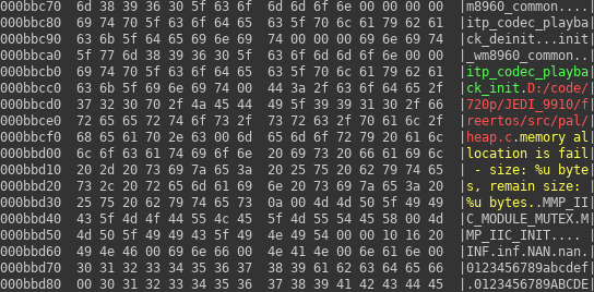
In the picture on the right one especially interesting information can be seen – it seems that as an operating system FreeRTOS was used. FreeRTOS is open source project, so its source code can be downloaded.

This information could be later possibly used to link compiled code with FreeRTOS source code. Let’s look into source code to find some useful location. As we already know the encoding of opcode for an operation on strings, finding some string in code might work. I was able to identify one such place in tasks.c file. It is shown on snippet below:

4110           if( ulStatsAsPercentage > 0UL )
4111           {
4112             #ifdef portLU_PRINTF_SPECIFIER_REQUIRED
4113             {
4114               sprintf( pcWriteBuffer, "\t%lu\t\t%lu%%\r\n", pxTaskStatusArray[ x ].ulRunTimeCounter, ulStatsAsPercentage );
4115             }
4116             #else
4117             {
4118               /* sizeof( int ) == sizeof( long ) so a smaller
4119               printf() library can be used. */
4120               sprintf( pcWriteBuffer, "\t%u\t\t%u%%\r\n", ( unsigned int ) pxTaskStatusArray[ x ].ulRunTimeCounter, ( unsigned int ) ulStatsAsPercentage );
4121             }
4122             #endif
4123           }
4124           else
4125           {
4126             /* If the percentage is zero here then the task has
4127             consumed less than 1% of the total run time. */
4128             #ifdef portLU_PRINTF_SPECIFIER_REQUIRED
4129             {
4130               sprintf( pcWriteBuffer, "\t%lu\t\t<1%%\r\n", pxTaskStatusArray[ x ].ulRunTimeCounter );
4131             }
4132             #else
4133             {
4134               /* sizeof( int ) == sizeof( long ) so a smaller
4135               printf() library can be used. */
4136               sprintf( pcWriteBuffer, "\t%u\t\t<1%%\r\n", ( unsigned int ) pxTaskStatusArray[ x ].ulRunTimeCounter );
4137             }
4138             #endif
4139           }
4140 
4141           pcWriteBuffer += strlen( pcWriteBuffer );
vTaskGetRunTimeStats printf format
vTaskGetRunTimeStats formatting strings

If we look at code before the snippet, we can see that the function is surrounded with ifdefs and is meant to be turned on only for demo purposes. Also searching for complete formatting string from sprintf function above fails on LKV373A firmware. Fortunately it is present in code and happens to have some modifications. One of them is the formatting string we were searching for. I was able to identify them starting at offset 0xbab2f. You can see it on hexdump. What is a bit surprising is that there are four such strings, while we expected only two in whole code. But "IDLE" string after them is confirming that it must be tasks.c module.

Now we can use method shown on previous tutorial about processor identification to find references to these strings. Finally I found usages of offsets 0xbab5c and 0xbab73 (marked in green and blue) near offset 0x91fd4.

At this moment, we have machine code and source code that is very likely to be compiled one to one into this machine code. We can also see here very useful side-effect of open source popularity: we have a system that has quite unusual function and is using open source software. So we can conclude that we can be almost sure that any random part of code also has open source software in itself.

Code patterns

As we already have quite reliable anchor for our analysis, we could try identifying more opcodes. But, to make things easier, I want to go the pattern matching way. Whichever architecture you analyze, you see some patterns that are same or almost the same on any architecture. This is especially true on RISC architectures, as they have very limited set of functions, so compiler have to join two or more instructions to get desired high level functionality. It this section, I will describe some of such patterns, I was able to identify and decode in LKV373A firmware. They are:

  • Function call
  • Function prologue and epilogue
  • Read-only memory access
  • Compare and jump
  • Variadic functions

Following is short description of the above patterns.

Function call

This is main element of ABI (Application Binary Interface) from the point of view of a programmer. Therefore it should also be well-known, even to people not involved in assembly programming or reverse-engineering. It is all about the method of passing arguments, before a call to a function.

Let’s see how such a call looks on MIPS architecture:

lw      gp,24(sp)
nop
lw      s0,-32736(gp)
nop
addiu   s0,s0,6872
lhu     s0,0(s0)
addiu   a0,sp,34        # a0 = sp + 34
move    a1,zero         # a1 = 0
li      a2,16           # a2 = 16
move    s7,v0
sh      s0,32(sp)
lw      t9,(get_sr_name_ptr - 0x1000BE50)(gp)
nop
jalr    t9

As we can see in case of MIPS, arguments are passed in registers named a0, a1, a2 and so on. Then address of function to call is loaded to t9 and jalr (jump and link register) is performed. Usually, in case of ABI, where arguments are passed in registers, when number of arguments is greater than number of such registers, they are passed through memory (i.e. stack).

Function prologue and epilogue

When performing a call to different function, state of the processor have to be preserved, so after the call it is again the same as before (with exception of few registers, used e.g. for return value passing). This operation may be done by caller or callee. Let’s look again at MIPS code to see how it works there:

sw      ra,5328(sp) 
sw      s8,5324(sp) 
sw      s7,5316(sp) 
sw      s6,5312(sp) 
sw      s1,5292(sp) 
sw      s0,5288(sp) 
sw      gp,5320(sp) 
sw      s4,5304(sp) 
sw      s3,5300(sp) 
sw      s2,5296(sp) 

I think there is nothing special to comment here. The opposite happens on function epilogue and additionally, immediately after that return instruction should appear.

Read-only memory access

This one is already partially analyzed on previous part of this series. It is usually appearing where some strings need to be used in code. Strings written in code as literals are stored in part of the memory where they shouldn’t be modified. Then theirs addresses are computed using some base register, or directly if code is not relocatable. This is how it works on MIPS:

lw      t9,-30404(gp)

But, as we can see on previous post, we have something missing on our mysterious architecture. There, address was computed as $3=$3+0xbadadd. So, we should expect that register used should be set to something before that.

Compare and jump

This is after calling conventions, another extremely popular scheme. It usually consists of two opcodes. At first two numbers are compared, and some flags in processor are set. Then based on the state of one of the flags, jump is performed, or processing is continued if flag has value different than we expect. This time, let’s see how it works on x86 platform, as MIPS uses a bit different philosophy:

cmp     [ebp+arg_4], eax
jnz     loc_404CEB

On x86 cmp instruction causes the subtraction of two parameters, without actually storing the result, but only updating the FLAGS register, so it is known if the value is zero, or the overflow happened, and so on. Then based on flag value (in this case if zero flag is not set), jump occurs, or not.

Variadic function

Variadic function is function that can get variable number of parameters. The most popular example of such function is printf. It accepts format string and parameters, which number depend on format string. On system, where parameters are passed through registers, I expect it to get format through register and rest of parameters through stack or dedicated structure, so generally memory. Once we know how constants are accessed, it should be quite easy to identify, as it most likely will get format string as one of the first parameters, and somewhere close to that parameters should be stored, one after another.

Identifying patterns

Now, as we know what pattern we will look for, it is time to find them in code and guess functions of particular opcodes.

Read-only memory access

Let’s look at area near reference to our format string:

00091FB8                 .word 0x1000000A         # 04: ? 0x0A
00091FBC                 .word 0xD401D00C         # 35: ? $0, $1, $26, 0x0c
00091FC0                 .word 0x18600010         # 06: ? $3, $0+0x10
00091FC4                 .word 0x1880000B         # 06: ? $4, $0+0x0b
00091FC8                 .word 0xD4012810         # 35: ? $0, $1, $5, 0x10
00091FCC                 .word 0xA8638608         # 2A: la $3, $3+0x8608
00091FD0                 .word 0x400268A          # 01: ? 0x268a
00091FD4                 .word 0xA884AB5C         # 2A: la $4, $4+0xab5c
00091FD8                 .word 9                  # 00: ? 0x09
00091FDC                 .word 0xBC160000         # 2F: ? $0, $22
00091FE0                 .word 0x18600010         # 06: ? $3, $0+0x10
00091FE4                 .word 0x1880000B         # 06: ? $4, $0+0x0b
00091FE8                 .word 0xA8638608         # 2A: la $3, $3+0x8608
00091FEC                 .word 0xA884AB73         # 2A: la $4, $4+0xab73
00091FF0                 .word 0x4002682          # 01: ? 0x2682
00091FF4                 .word 0x15000000         # 05: ?

After splitting instruction words into parts and decoding opcode, register and immediate values, we can see that string’s address is based on register $4 and stored also in register $4. If we look few lines upwards, we can see that register $4 is computed based on register $0 and offset 0x0b (marked in orange). Register $0 is often used to always store value 0. Now, if we look at original offset of string in firmware, we can see that it is 0xbab5c! So that instruction must store immediate value in register’s higher half. Therefore we just guessed function of opcode 06. Later this opcode will be described as lh (load high).

By the way we also discovered that almost surely firmware image is mapped to address 0 after loading to operational memory or more likely mapping EEPROM to address space.

Compare and jump

In the snippet above, another one thing is quite interesting. And weird at the same time. There are few instructions that seem to not contain any register encoded and have weird uneven offsets, often with quite low values. At this moment my theory is that shorter ones are some kind of jumps (like 0x91fd8) and longer ones are function calls (like 0x91fd0). Then it is time to try to find compare and jump pattern.

If we are right, then opcodes like 00, 04 are jumps and 01 means a call. After this section we should also tell conditional and unconditional jumps apart.

Ok, so we now need to go back to source code and find some good candidate for conditional jump. It should be as close to format string as possible. If we look at the snippet from Identifying target section, we can see one such check on line 4110. It checks for value being greater than zero. Going upwards a little bit, we encounter one 04 opcode, immediately preceded by 2F instruction:

00091FB0                 .word 0xD4011808         # 35: ? $0, $1, $3, 0x08
00091FB4                 .word 0xBC050000         # 2F: ? $0, $5
00091FB8                 .word 0x1000000A         # 04: ? 0x0A
00091FBC                 .word 0xD401D00C         # 35: ? $0, $1, $26, 0x0c
00091FC0                 .word 0x18600010         # 06: ? $3, $0+0x10
00091FC4                 .word 0x1880000B         # 06: ? $4, $0+0x0b

Now, if we look at occurrences of 2F opcode, we can spot that it is appearing usually near 04 opcode. However we cannot tell that they appear in exactly this order which is quite weird. On the other hand if we look at register this particular occurrence uses, it is quite likely it is compare opcode.

If we assume that 2F is cmp (compare) and 04 is jg (jump greater), we see that this more or less matches behavior we expect from the code immediately preceding sprintf from FreeRTOS source code.

However we still miss one information: what does the offset mean. If it is jump instruction, then we cannot jump 10 bytes ahead, because we would land in the middle of instruction. If we look again at source code, we can see that our jump should not go very far forward, so value should also not be too high. We can also exclude usage of register as address, because it would be register $10, which is not set anywhere near jump.

Having no other idea, I did an experiment. I multiplied jump value by 4, because length of instruction is always 4 and added next instruction address to result. Then I checked what is there and… bingo! It jumped above the sprintf call and ended up immediately after it. Some time later, I discovered that it is not completely truth. It happens that real formula is:

addr = imm * 4 + PC

Where imm is instruction argument and PC is program counter before executing the instruction (so address of jump opcode).

The question still is how more sophisticated compares are performed, because every one I’ve seen is just telling which value is greater. As there does not seem to be any flag in instruction, maybe there is no other option and to do that some arithmetic operation must be done to bring them to greater than operation?

Function call

Another thing, we can learn near the sprintf function is how parameters are passed to function. Signature for sprintf is:

int sprintf(char *str, const char *format, ...);

So after analyzing its call, we should know how at least two first parameters are passed. Let’s see how it looks like in machine code:

00091FC0  .word 0x18600010  # 06: lh $3, $0+0x10
00091FC4  .word 0x1880000B  # 06: lh $4, $0+0x0b
00091FC8  .word 0xD4012810  # 35: ? $0, $1, $5, 0x10
00091FCC  .word 0xA8638608  # 2A: la $3, $3+0x8608   # 0x108608 = pcWriteBuffer?
00091FD0  .word 0x400268A   # 01: call +0x268a       # 0x9b9fc = sprintf
00091FD4  .word 0xA884AB5C  # 2A: la $4, $4+0xab5c   # 0xbab5c = "%-16s %c %7u%s\t%2u%%\r\n"

Here, another interesting detail appears: last instruction setting the registers appears after the actual call. This is perfectly normal and can also be found on MIPS architecture. Its purpose is to allow concurrent execution of the two instructions.

Variadic functions

Now, if we scroll a bit upwards, we can see some interesting bunch of 35 opcodes. We know, that our call should have more than 2 parameters and thanks to format string we can tell that there should be exactly 5 extra parameters. Now if we count number of 35 opcodes, we see that these numbers match.

00091FA8  .word 0xD4012000  # 35: ? $0, $1, $4, 0x00
00091FAC  .word 0xD401A004  # 35: ? $0, $1, $20, 0x04
00091FB0  .word 0xD4011808  # 35: ? $0, $1, $3, 0x08
00091FB4  .word 0xBC050000  # 2F: cmp $0, $5
00091FB8  .word 0x1000000A  # 04: jg 0x91fe0
00091FBC  .word 0xD401D00C  # 35: ? $0, $1, $26, 0x0c
00091FC0  .word 0x18600010  # 06: lh $3, $0+0x10
00091FC4  .word 0x1880000B  # 06: lh $4, $0+0x0b
00091FC8  .word 0xD4012810  # 35: ? $0, $1, $5, 0x10
00091FCC  .word 0xA8638608  # 2A: la $3, $3+0x8608
00091FD0  .word 0x400268A   # 01: call 0x9b9fc
00091FD0                    #   sprintf(pcWriteBuffer, "%-16s %c %7u%s\t%2u%%\r\n",
00091FD0                    #     $4, $20, $3, $26, $5)
00091FD4  .word 0xA884AB5C  # 2A: la $4, $4+0xab5c

So, we can tell almost for sure that opcode 35 gets value of third register parameter and stores it at address computed as follows:

addr = reg1 + reg2 + imm

So e.g.

*($0 + $1 + 0x0c) = $26

Unfortunately with only that information, we can only guess the order of parameters, i.e. if $4 is first parameter or last one.

For future, we will denote opcode 35 as sw (store word).

Function prologue and epilogue

As we know exactly at which address the call will land, we can try to decode function prologue and epilogue, so what happens just after the call and just before returning back. Let’s see how such part of code looks, for example of sprintf function:

0009B9F0           .word 0x44004800  # 11: ret
0009B9F4           .word 0x8441FFF8  # 21: ? $2, $1, -0x08
0009B9F8 sprintf:  .word 0xA9030000  # 2A: la $8, $3
0009B9FC           .word 0x18600010  # 06: lh $3, $0+0x10
0009BA00           .word 0xD7E14FFC  # 35: sw $31, $1, $9, -0x04
0009BA04           .word 0xD7E117F8  # 35: sw $31, $1, $2, -0x08
0009BA08           .word 0xD7E10FF4  # 35: sw $31, $1, $1, -0x0c

And to confirm it is the reverse at the end, let’s see epilogue:

0009BA60           .word 0x8521FFFC  # 21: ? $9, $1, $31, -0x04
0009BA64           .word 0x8421FFF4  # 21: ? $1, $1, $31, -0x0c
0009BA68           .word 0x44004800  # 11: ret
0009BA6C           .word 0x8441FFF8  # 21: ? $2, $1, -0x08

By the way immediately after sprintf there is strlen function, that is also called by function we are analyzing. So we see that registers stored with sw instructions are then recovered by opcode 21. Then we can safely assume it is reverse and denote it as lw (load word).

And we see that last jump in function is done by opcode 11, so we can denote it as ret (return). I still don’t know what is the meaning of its parameters. If we use standard decoding, it would be:

ret $0, $0, $9, 0x00

But I have no proof that it is the real meaning. I only see that sometimes this third hypothetical register have different value, but usually it is $9.

From my experience register saving, we see here is done to stack. If in this case it is also true, then we have two options for stack pointer: $1 and $31. Some more investigation must be done to tell which one is SP.

Other methods

We can also try to find constants other than strings. Then we have a chance, that there will be some arithmetic operation going on with them. Personally, I haven’t tried that approach, so I can’t show any example.

Another method might be finding references to some known structures. We can see one such structure in the function, we analyzed (TaskStatus_t). This is also left as an exercise to the reader.

Conclusion

Main focus of the analysis was on branching. As shown, we know quite a lot about not only branching, but also whole ABI. Now it should be possible, as soon as main entry of the system is found, to discover complete flow of the program.

We now know that first parameters are passed in registers $3, $4 and possibly so on. After analysis of function prologue and epilogue, we also know that here callee is responsible for preserving register values.

To sum up, we already know following instructions:

  • 00: jmp off
  • 01: call off
  • 03: j? off
  • 04: jg off
  • 06: lh $r1, $r2, imm
  • 11: ret
  • 21: lw $r1, $r2, $r3, imm
  • 2A: la $r1, $r2, imm
  • 2F: cmp $r1, $r2
  • 35: sw $r1, $r2, $r3, imm

We also know that in this architecture, there is mechanism of slots, identical with that in MIPS. Together with fixed-sized instructions and opcode and register field lengths, it is really similar to MIPS. Unfortunately it is not exactly the same, so reverse engineering of ISA have to be continued.

Unfortunately, after doing the research described here, I see that tools I used are not enough to do more reversing efficiently. So, before doing one step forward, I have to find a way to introduce more automation to the process. As soon as I succeed with this, I will write next part, so stay tuned!

Posted in Reversing LKV373A, TutorialsTagged assembly, English, FreeRTOS, hardware, Reverse EngineeringLeave a comment

[Import]LKV373A HDMI to Ethernet converter: firmware image format

Posted on September 4, 2017 - October 17, 2019 by Kamil (aka. v3l0c1r4pt0r)

NOTE: This post was imported from my previous blog – v3l0c1r4pt0r.tk. It was originally published on 19th August 2017.

This article is part of series about reverse-engineering LKV373A HDMI extender. Other parts are available at:

  • Part 1: Firmware image format
  • Part 2: Identifying processor architecture
  • Part 3: Reverse engineering instruction set architecture
  • Part 4: Crafting ELF
  • Part 5: Porting objdump
  • Part 6: State of the reverse engineering
  • Part 7: radare2 plugin for easier reverse engineering of OpenRISC 1000 (or1k)

Recently, I bought LKV373A which is advertised as HDMI extender through Cat5e/Cat6 cable. In fact it is quite cheap HDMI to UDP converter. Unfortunately its inner workings are still more or less unknown. Moreover by default it is transmitting 720p video and does not do HDCP unpacking, which is a pity, because it is not possible to capture signal from devices like cable/satellite TV STB devices. That is why I started some preparations to reverse engineer the thing.

Fortunately a few people were interested by the topic before (especially danman, who discovered second purpose for the device). To make things easier, I am gathering everything what is already known about the device. For that purpose I created project on Github, which is to be served as device’s wiki. Meanwhile I was also able to learn, how more or less firmware container is constructed. This should allow everyone to create custom firmware images as soon as one or two unknowns will be solved.

First one is method for creation of suspected checksum at the very end of firmware image. This would allow to make modifications to filesystem. Other thing is compression algorithm used to compress the program. For now, it should be possible to dissect the firmware into few separate fragments. Below I will describe what I already know about the firmware format.

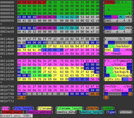
ITEPKG

ITEPKG format (container content discarded)

Whole image starts with magic bytes ITEPKG, so this is how I call outer container of the image. It allows to store data of few different formats. Most important is denoted by 0x03 type. It stores another data container, that is almost certainly storing machine code for bootloader, and another entity of same type that stores main OS code. This type is also probably storing memory address at which content will be stored after uploading to device. Second important entity is denoted by type 0x06 and means regular file. It is then stored internally on FAT12 partition on SPI flash. There is also directory entry (0x05), that together with files creates complete partition.

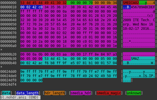
SMEDIA

SMEDIA container (header truncated)

Another data container mentioned on previous section is identifiable by magic SMEDIA. It consists of two main parts. Their lengths are stored at the very beginning of the header. First one is some kind of header and contains unknown data. Good news is that it is uncompressed. Second one is another container. Now the bad news is that it contains compressed data chunks.

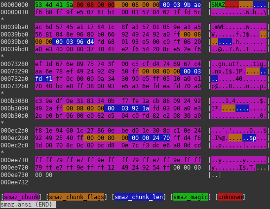
SMAZ

SMAZ container

This container’s function is to split data into chunks. One chunk has probably maximum length of 0x40000 bytes (uncompressed). Unfortunately after splitting, they are compressed using unknown algorithm, behaving similarly to LZSS and I have some previous experience with variant of LZSS, so if I say so it is very likely that it is true πŸ™‚ . As for now, I reached the wall, but I hope, I’m gonna break it some time soon. Stay tuned!

Posted in Reversing LKV373A, UncategorizedTagged English, hacking, hardware, Reverse EngineeringLeave a comment

[Import]Understanding JCOP: pre-personalization

Posted on September 4, 2017 - September 10, 2017 by Kamil (aka. v3l0c1r4pt0r)

NOTE: This post was imported from my previous blog – v3l0c1r4pt0r.tk. It was originally published on 25th July 2017.

As I promised some time ago, now I am going to describe process of pre-personalization of a JCOP card. JCOP is one of the easier to get JavaCard-compatible cards. However they cost a bit. The problem with the ones available from eBay sellers is lack of pre-personalization. Ok, there are some advantages of buying not pre-personalizaed card, like ability to set most of its parameters, but by the way it is quite easy to make such card unusable.

Online resources, as I mentioned in the first part of the tutorial, are not very descriptive. They say that there is such thing like pre-personalization and it has to be done before using the card, flashing applets, using them and so on. There is only one source that helps a little bit. Someone has written script for the process. However there are two problem with the script. The first one is that it is written in some custom language and internet does not know about the interpreter, it is probably something provided by NXP – manufacturer of JCOP for its customers and neither me nor (probably) you, reader, are their customers. The consequence is that we can have script in custom language, with commands like ‘/select’ or ‘/send’. Fortunately, documentation of ISO 7816 (smart card connection), allows to decipher this. So this problem could be finally solved. Another problem is lack of command values and addresses in memory, so we do not know where and how to read/write/execute anything. After really deep search in Google, finally, I was able to find out all the missing values, so this tutorial could be written.

Process overview

Ok, after this way too long historical introduction, let’s see what will be needed. I assume, you are already able to communicate with your card using raw PDUs. If you don’t, up to this point there are quite a few resources to learn from, so I will not describe this. The most important thing here is to have so called transport key (KT). If you do not have it, go get it now. Seller should provide it to you, and if he did not, you are stuck, since the first step requires this key.

So, basically steps will be as follows:

  1. Select root applet with Transport Key
  2. Boot the card
  3. Read/write some data
  4. Protect the card
  5. Fuse it

Easy? Easy. But only if you know some hex numbers. Ok, here, one big WARNING: the last step is irreversible and can be done by mistake quite easily, so think twice before sending anything, and if you are sure, that you are done, think twice again, before issuing it.

Pre-personalization, step by step

At first, we use Transport Key to select proper applet. Format of SELECT command is as below:

CLA=00 INS=A4 P1=04 P2=00 Lc=10 (...)

Where CLA is always zero, INS means SELECT, P1, according to ISO7816 means selection by DF name and Lc is length of KT. After that, key have to be appended. Of course, whole APDU is to be given to communications program as binary values or hex values only.

What now follows is specific to NXP cards only and is mostly undocumented publicly. First of such commands is BOOT command. Its format is as follows:

CLA=00 INS=F0 P1=00 P2=00

Now double care have to taken, because FUSE command should be available after this point and its APDU consists only of zeros, so every mistake might make the card unusable, since security keys are generated randomly for each card.

Reading memory

Now the most important values to read are called CM_KEY and GPIN in memory dump, I shared in the previous post on the topic. First one starts at offsets: 0xc00305, 0xc00321 and 0xc0033d and are 0x10 bytes long. The other one can be found at offset 0xc00412 and by default should be 5 bytes long. However maximum length is also 0x10, so it is better to make sure the length is really 5 by reading byte at offset 0xc00407. To sum up following commands need to be issued and results be saved for future use:

CLA=C0 INS=B0 P1=03 P2=05 Lc=10
C0 B0 03 21 10
C0 B0 03 3D 10
C0 B0 04 07 01
C0 B0 04 12 xx

Where CLA + P1 + P2 is concatenated address of memory area to read, INS=B0 is read command and Lc contains length of data to read.

Writing data

Alternatively, it is possible to write custom values to these buffers. This is especially encouraged for users who want to use the card not only for testing. Overwriting the values could be done with following:

CLA=C0 INS=D6 P1=03 P2=05 Lc=10 (...)
C0 D6 03 21 10 (...)
C0 D6 03 3D 10 (...)
C0 D6 04 12 05 (...)

Where user data is filled with some random data of length in Lc field.

Required values

Beside securing keys, it is required to set CM_LIFECYCLE value to 0x01 and make sure all fields related to keys and PIN have proper values. Here, my memory dump can be used as reference, since I initialized the card before dumping the memory.

Finishing

After setting all the fields to desired values, there are two more steps to do. First one is issuing PROTECT command. It looks as below:

CLA=00 INS=10 P1=00 P2=00

And finally, sending FUSE command with:

CLA=00 INS=00 P1=00 P2=00

Here again, remember, that this command cannot be undone!

Well done! Your card should now be pre-personalized and ready to use, even in production environment. At the end, one remark: probably FUSE command does not need to be issued at all. However, if it is not issued, the card is completely insecure and should not be used in production.

Previous part of this tutorial can found under this link.

Posted in Tutorials, Understanding JCOPTagged electronics, English, hacking, hardware, JavaCard, JCOP, Reverse Engineering, smart card1 Comment

[Import]Understanding JCOP: memory dump

Posted on September 4, 2017 - September 10, 2017 by Kamil (aka. v3l0c1r4pt0r)

NOTE: This post was imported from my previous blog – v3l0c1r4pt0r.tk. It was originally published on 8th February 2017.

Some time ago I was struggling with JCOP smart card. The one I received as it turned out was not pre-personalized, which means some interesting features (like setting encryption keys and PIN) was still unlocked. Because documentation and all the usual helpers (StackOverflow) were not very useful (well, ok, there was no publicly available documentation at all), I started very deep search on Google, which finished with full success. I was able to make dump of whole memory available during pre-personalization.

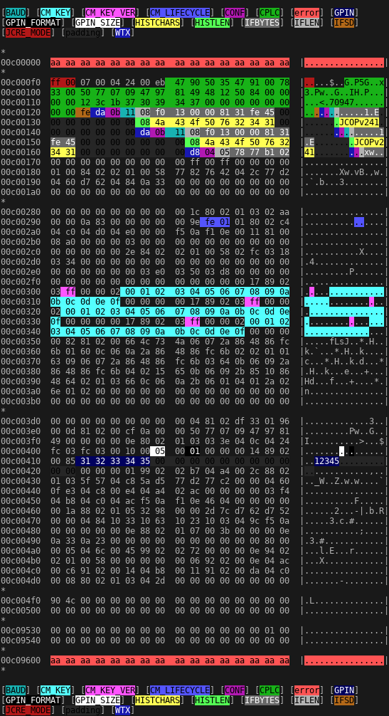
Since it is not something that could be found online, here you have screenshot of it, colored a bit with help of my hdcb program. Without documentation it might not be very useful, but in some emergency situation, maybe somebody will need it.

JCOP memory dump made at the very beginning of pre-personalization

Small explanation: first address, I was able to read was 0xC000F0, first address with read error after configuration area was 0xC09600. I know that, despite of lack of privileges some data is placed there.

There are three configurations: cold start (0xc00123-0xc00145), warm start (0xc00146-0xc00168) and contactless (0xc00169-at least 0xc0016f). Description of coding of the individual fields is outside of the scope of this article. I hope, I will describe them in future.

Next time, I will try to describe the process of pre-personalization, that is making not pre-personalized card, easy to get from usual sources of cheap electronics, able to receive and run applets.

Update: Next part of this tutorial can be found under this link.

Posted in Tutorials, Understanding JCOPTagged electronics, English, hacking, hardware, JavaCard, JCOP, Reverse Engineering, smart cardLeave a comment

[Import]Airlive WN-151ARM UART pinout & root access

Posted on September 4, 2017 - September 7, 2017 by Kamil (aka. v3l0c1r4pt0r)

NOTE: This post was imported from my previous blog – v3l0c1r4pt0r.tk. It was originally published on 24th November 2015.

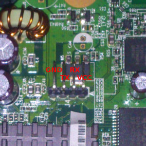
Airlive WN-151ARM pinout

For curious ones. Here is pinout of serial connection. As you can see UART pins are at J4 header (should have pin 4 labeled and 1 be square).

J4 header
Num. Function
1 VCC
2 RX
3 TX
4 GND

Edit: Oh, and one more thing: goldpin header, you see in the picture is soldered by me, so do not be surprised if you have to hold wires all the time during the transmission.

Root access

There is also possibility to gain root access without removing the cover and possibly voiding the warranty. You have to connect to router’s AP and enter

http://192.168.1.254/system_command.htm

into your browser (panel authentication required). Now you can execute any command you want with root privileges! So let’s type

/usr/sbin/utelnetd -d &

into Console command field and press Execute button. If everything went well, you should now be able to connect to your router using telnet at its default TCP port 23. After that you should see BusyBox banner and command prompt.

It is worth noting that this hidden console cannot be accessed by unauthorized person, so only router administrator can use this (in theory, in practice there are surely a lot of routers using default credentials and security of httpd binary is unknown).

Posted in RandomTagged Airlive, backdoor, electronics, hacking, hardware, Linux, pinout, UARTLeave a comment

[Import]TP-Link TD-W8901G UART pinout

Posted on September 4, 2017 - September 7, 2017 by Kamil (aka. v3l0c1r4pt0r)

NOTE: This post was imported from my previous blog – v3l0c1r4pt0r.tk. It was originally published on 31st May 2014.

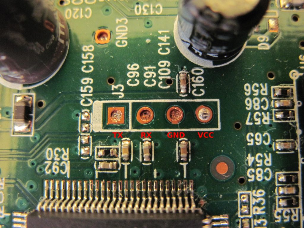
Some people might wonder: what is the pinout of my router’s serial connection. If you’re a happy owner of TP-Link TD-W8901G and asking that yourself, here is the answer:

TP-Link TD-W8901G’s pinout

In the link below there is also this router’s pinout and moreover author states that to make that port working there is a need to modify some resistors. I have V3.5 of that router and didn’t notice any mod to be necessary.

It is possible to solder goldpins in here and router so far haven’t fried. Of course you can try communicating without stable connection and it even works but after training your fingers while waiting for the firmware download/upload to complete you’ll change your mind, I guarantee:).

PS: that model is the one that was one of the victims of massive DNS changing some time ago so if this is the one you’re using as your bridge to the Internet you may be also interested in this.

PS2: if you have another router and want to find out what is the serial port pinout I recommend going here.

Posted in RandomTagged electronics, English, hardware, router, TP-Link, UARTLeave a comment

[Import]Graphic LCD based on ST7565 chip under Raspberry Pi

Posted on September 4, 2017 - September 7, 2017 by Kamil (aka. v3l0c1r4pt0r)

NOTE: This post was imported from my previous blog – v3l0c1r4pt0r.tk. It was originally published on 25th December 2013.

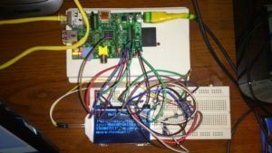
Hi, today I’d like to show you how to connect and use gLCD module with Raspberry Pi as host. The display I have is only bare display without any board not like the one in Adafruit’s offer. It can be powered by 3V3 Raspberry but the display itself needs a bit more power so we will need a few capacitors to build a circuit for that purpose. It will also make the connection a bit complicated (can be seen in the photo on the right). Nevertheless I think that the process is still rather easy.

Overview

Connected display

As far as I know ST7565 based displays can be connected on two ways: parallel and serial. In case of serial connection, which I used to save few GPIO’s, it is possible to program it using SPI or just only GPIO’s. The display that I have is a bit different than most of the others because it has external backlight, which is additionally single LED so it is very power-saving (15mA). The only problem with that backlight was that the vendor didn’t told anything about parameters of that diode so I needed to figure it out myself.. The second problem while connecting the display itself might be amount of cables that need to be connected when using breadboard. Despite these two facts the whole process should be easy.

Physical connections

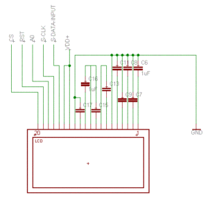
Connection scheme

As said before the only step that may be a bit complicated is connecting so called step-up voltage circuit, made of 4 capacitors. The capacitors that we will use are 1uF electrolytic caps. Beside that we need to use another 5 caps (same as before) to connect parallel inputs to ground. So in sum we need 9 of them. Now we only need to connect VDD to 3V3 pin on Raspberry, ground from the schematic on the right with GND pin, SDATA to SMOSI on Pi, SCLK to SCLK and A0, RST and CS to any free GPIO. It is good to remember their numbers cause we will need it in a moment πŸ™‚ It is important to use numbers used by Linux kernel, not wiringPi which has its own names. At last we need to connect the backlight. As said I have ECO backlight so I had to connect mine using 10 Ohm resistor. You can connect it to 3V3 or if you like to have control during runtime use GPIO, just like any other LED.

Configuring the program

Now I have to mention something about a program itself, because depending on how your vendor implemented the things your display will almost surely need a bit different settings. General procedure will look the same on every ST7565-based display. Main differences will be on particular commands during setup procedure.

 
uint8_t init() 
{ 
  if (!bcm2835_init()) { 
    return 0; 
  } 
  bcm2835_gpio_fsel(LCD_BACK,BCM2835_GPIO_FSEL_OUTP);   //backlight 
  bcm2835_gpio_fsel(LCD_A0,BCM2835_GPIO_FSEL_OUTP);   //A0 
  bcm2835_gpio_fsel(LCD_RST,BCM2835_GPIO_FSEL_OUTP);    //RST 
  bcm2835_gpio_fsel(LCD_CS,BCM2835_GPIO_FSEL_OUTP);   //CS 
  bcm2835_gpio_write(LCD_CS,HIGH);        //set CS to high to indicate the bus as free 
  bcm2835_gpio_write(LCD_RST,LOW); 
  bcm2835_delayMicroseconds(1); 
  bcm2835_gpio_write(LCD_RST,HIGH);       //hardware reset 
  //setup SPI 
  bcm2835_spi_begin(); 
  bcm2835_spi_chipSelect(BCM2835_SPI_CS_NONE);      //manual CS control 
  bcm2835_spi_setClockDivider(BCM2835_SPI_CLOCK_DIVIDER_4); //set speed to 62.5MHz (fastest supported) 
 
  int i; 
  bcm2835_gpio_write(LCD_CS,LOW); 
  for(i = 0; i < sizeof(initcmd)/sizeof(uint8_t); i++) 
    transfer(initcmd[i],0); 
  bcm2835_gpio_write(LCD_CS,HIGH); 
  bcm2835_gpio_write(LCD_BACK,HIGH);        //turn backlight on 
 
  return 1; 
} 

I think that the code above should be generally clear. The most important for us is for loop that is executing every byte from initcmd array. Its content will look like that:

const uint8_t initcmd[] =
{
  0xa1,             //screen orientation
  0x41,             //set starting line
  0xc0,             //page count direction
  0xa3,             //1/7 bias
  0x2c,             //vc
  0x2e,             //vc+vr
  0x2f,             //vc+vr+vf
  0x24,             //voltage regulator (0x20-0x27)
  0xa6,             //do not reverse the display
  0xaf,             //display on
  0xa4,             //display from ram
  0x81,             //turn on brightness regulation
  0x18              //set brightness (0x0-0x40)
};

The most important values here are:

  • voltage regulator – 0x20 means the darkest, as seen above in my case 0x24 worked
  • bias – I saw displays that had 1/9 so you need to make sure how is in yours and set it according to chips documentation linked at the end

You may also want to play with commands like screen orientation, page direction, display reverse or brightness to fit them to your needs. Now you have tell the program which GPIO you used as backlight (if you weren’t using GPIO you will now need to comment out few lines that sets backlight up), CS, RST and A0.

The program itself

To compile the program you will need to use external library named libbcm2835. It can be installed on ArchLinux ARM by issuing pacman -S libbcm2835 as root. If you are ready you can compile the program by typing: gcc -o lcd lcd.c -lbcm2835 assuming you didn’t change the filename. The simple program I’ve written, basing on the one posted on Gist by tmeissner here and ST7565’s documentation supports transferring single byte (commands too), whole framebuffer, or writing 5×8 single ASCII character or character string. Basing on both codes: mine and Meissner’s I think it is possible to do anything you could think about with that display.

Font creation

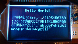
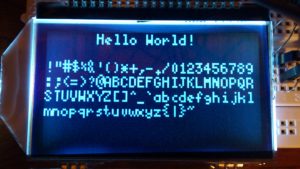
Standard ASCII table and traditional β€˜Hello World!’:)

Ending slowly it’s time to tell something about fonts. As I said it is possible to simply write characters on the screen. To understand how all that thing works you need to know how the pixels are transfered to the display. The best explanation of the ST7565 display’s work can be in my opinion found here. TL;DR: the whole pixel space is divided into eight, 8-pixel high, horizontal pages divided into 128 columns that are 8 pixels high. If you didn’t understand, try link above. Nevertheless single letter is 8-pixel high and 5-pixel long so we need 5 bytes to store one letter. Its pixel map starts at left, top corner so it’s our (0,0) point and setting LSBof the first byte lights highest pixel. The font that is available in the code is Fixed 5×8 if someone is curious, it’s one of the default fonts in Xorg. To speed up conversion of the font to the display’s format I made simple OpenGL program to do the job for me. The code is of course available to download (check out my github).

DLs

Traditionally, at last some downloads:

  • First, and most important: C code of my program
  • ST7565 documentation can be found here

Posted in TutorialsTagged electronics, English, hardware, LCD, Linux, Raspberry Pi1 Comment

[Import]Using GNU Radio Companion – simple FM radio tutorial

Posted on September 4, 2017 - September 6, 2017 by Kamil (aka. v3l0c1r4pt0r)

NOTE: This post was imported from my previous blog – v3l0c1r4pt0r.tk. It was originally published on 1st November 2013.

This post is the second part of the Instructable mentioned on the previous post. That’s tutorial on how to make simple FM radio using GRC. That task is in my opinion the simplest project that can be made using GRC so it’s in fact beginners guide to GNU Radio which is really capable software. I hope that it is only the first my project using that software.

It isn’t hard to find GRC projects that implements FM radio functionality, that’s a fact. But when it comes to reproduce them so they are working just like SDR# you’d realize it’s a bit harder task. At least I did. I found about a three such projects but there was never any included project file and the only materials was video or pictures. I admit the video has pretty good explanation but it still wasn’t enough. The rest was even worse. They were only blog posts with few screen shots and short description. So finally to reproduce functionality of SDR#’s FM radio I had to think on my own. And after few hours I did what I tried to do.

A bit of theory

RTL-SDR Source Properties

But let’s start at the beginning. The first thing that you need to do to start creating your own FM receiver using GRC is to find FM station that can be received without disruptions so you can check if your program works as well as i.e. SDR#. It can be done with help of SDR# and when you found one you are ready to learn some theory about FM signal processing. In fact it could be omitted, but in my opinion it is better to know a bit. I personally am not any specialist in radio theory so it will be really simple and I might be wrong somewhere so if you find any mistake in that what I will write here just let me know in comments.

The simplest FM radio consists of few elements:

  • signal source – in our case it would be RTL-SDR dongle
  • low pass filter
  • WBFM demodulator
  • audio output – your PC’s sound card

There can be few other elements depending on input and output sample rate, if it will be possible to match them using only above elements there won’t be any other. So our task will be getting signal using RTL-SDR, passing it through low pass filter and FM demodulator and outputting on PC’s sound card. Meanwhile we will also need to match the sample rate of the input to the one of the output (2 MHz in to 48 KHz out). All elements of this circuit can be found by writing part of its name while list on the right is selected. Element’s names are the ones used as section header below.

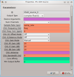
RTL-SDR source

Low Pass Filter Properties

Our signal input. We need to set its sample rate to 2M. It can be done by editing samp_rate variable and setting its value to 2e6. We need also to set the frequency of the station we want to receive. It is good practice to add every value that might be changed in the future as standalone variable. This can be done by adding Variable block from Variables category or, if you want to have possibility to edit it during the runtime block named WX GUI Slider or WX GUI Text Box and then just writing variable name as value in block’s properties.

Rational Resampler

Now we need to convert sample rate from 2M (samp_rate) to 500K which I realized is the best value for low pass filter’s input rate. To do that we need to add another variable, named i.e. quadrature, set its value to 500e3 (means: 500K). With that we need to add rational resampler’s block and set its decimation value to int(samp_rate/quadrature). Of course its input on the schematic should be connected to output of RTL-SDR Source (can be achieved by clicking on blue out on one block and then blue in on another).

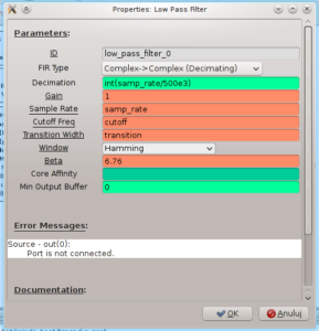
Low Pass Filter

The next step is to filter out frequencies other than the one we centered in th previous step. In that task we will use a low pass filter block. We here set cutoff frequency to 100e3. This is because that’s standard band’s width. I don’t know what correct value for transition width should be, but trying to change that I found that the higher value the better so it’s finally set to 1M. Obviously it should be connected to resampler’s output.

WBFM Receive

Volume slider Properties

Now we could do the nearly final and the most important step: placing the FM demodulator. In my case its quadrature rate equals 500k (that’s the same value as before so I set this to the value of quadrature variable). I don’t know if it could be changed to something else so if you are not sure just leave it as is. In that setting it should work.

Next Rational Resampler and Multiply Const

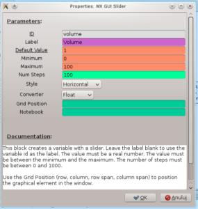
These elements’ job is to match the signal’s rate to the one supported by sound card and provide volume regulation. At first we need to convert rate from 500k to 48k so we need to decimate by 500 and then multiply by 48. In the second block we set const to volume. Now we can create variable or place WX GUI Slider with variable name set to volume. As you can see here color of WBFM demodulator is different than rational resampler’s and multiplier’s in and out. To change that you need to select them and use up and down arrows on your keyboard.

Audio Sink

That one’s function is to output signal on our sound card. Now its only required to edit its rate and choose 48k from a drop down list and that’s it! If you don’t have that option just choose the biggest value and edit value in rational resampler and it should work. Now you should be able to execute your program and test if it works. To hear anything it will probably be required to increase volume to about 50.

Finally: some links

If you don’t know how some part has been done or what value should have a particular variable below you can download projects that I’ve made first learning to use GRC myself and then preparing this tutorial. There is one project presented here and one made earlier.

Finished FM radio schematic

Posted in TutorialsTagged English, FM, GNU Radio, GRC, hardware, Linux, radio, RTL-SDR, SDR14 Comments

Posts navigation

Older posts
Newer posts

Tags

Android assembly busybox C CAN can-hacking cc-factory cmake compiler docker Dreamspark electronics English gcc hacking hardware JavaCard JCOP kernel KiCAD library Linux PC PCB pinout PKI polski programming Python radio Raspberry Pi Reverse Engineering RTL-SDR SDC SDM SDR smart card software tor tty UART UEFi Windows X.509 Xperia Pro

Recent Posts

  • PHP build for use bundled in Android applications
  • Running graphical apps inside Docker containers
  • Plugin architecture demo for Python projects
  • Authorizing adb connections from Android command line (and making other service calls from cli)
  • How to recover torrent from rtorrent meta files

Recent Comments

  • pomi on Playing with GF-07 GPS device
  • pomi on Playing with GF-07 GPS device
  • Hamdy Abumgata on Playing with GF-07 GPS device
  • Mousum Gogoi on Playing with GF-07 GPS device
  • Eason on Sniffing USB traffic with DSLogic logic analyzer into pcap file

Categories

  • News
  • Random
  • Reversing LKV373A
  • Setting up new v3 Hidden Service with ultimate security
  • Tutorials
  • Uncategorized
  • Understanding JCOP

Links

  • Me @ github
  • LKV373A Wiki
  • DevTomek

Archives

  • December 2024
  • November 2024
  • May 2024
  • July 2023
  • October 2022
  • August 2022
  • July 2021
  • June 2021
  • May 2021
  • December 2020
  • November 2020
  • October 2020
  • August 2020
  • December 2019
  • November 2019
  • October 2019
  • August 2019
  • July 2019
  • February 2019
  • November 2018
  • October 2018
  • June 2018
  • May 2018
  • March 2018
  • February 2018
  • January 2018
  • December 2017
  • November 2017
  • September 2017

Meta

  • Log in
  • Entries feed
  • Comments feed
  • WordPress.org
Proudly powered by WordPress | Theme: micro, developed by DevriX.