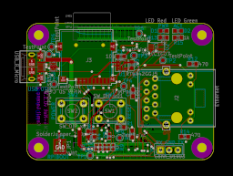
Few days back I published a hint that I am working on some hardware project, that utilized some networking, by publishing KiCAD footprints of connectors that I use. Now the time has come to reveal all the details. This was possible due to board being basically working.
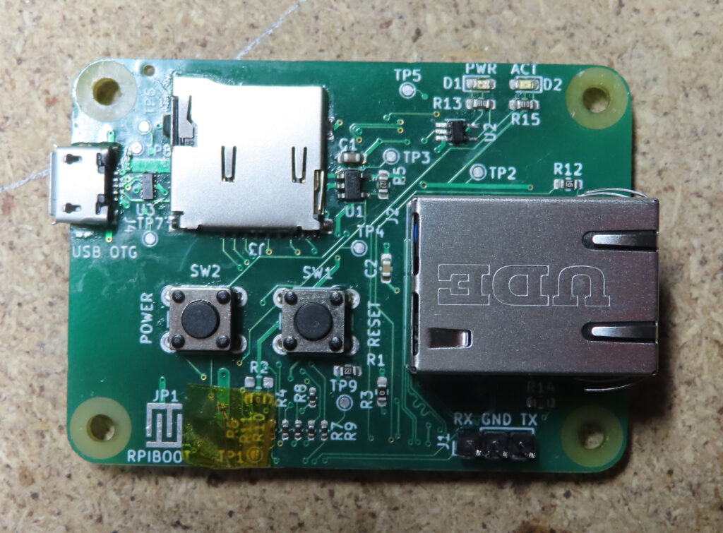
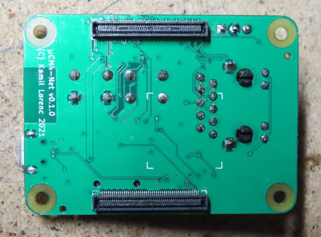
And the project is Raspberry Pi Compute Module 4 carrier/base board. Just to give a brief here, it is a board that is meant to allow connecting CM4 SoM modules to network and take as little space as practically possible. I would call this device smallest possible CM4 carrier board, but then probably somebody will prove me wrong by designing something smaller. But to still be practical, it is almost the smallest it could, as it is exactly same footprint as CM4 itself. By making it even smaller, I would have to remove mounting holes, as they are exactly at the edges.
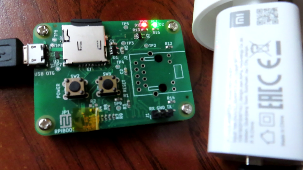
Getting to the interesting part, it is meant to connect to Ethernet and allow you to do whatever you like. The only thing you need to connect beside Ethernet is power via Micro USB connector. Worth to mention is that this is requirement of this particular iteration of the board, as it should be fairly easy to redesign it a bit to use PoE instead. Anyway, comparing to traditional Raspberry Pi, you get a lot of saved space at a cost of only 3 connector available (not counting UART header). And third, not mentioned yet, is microSD card slot, that is completely optional, but present in my case, as I use CM4Lite variant with no storage, so this is rather a useful feature. Getting rid of this requirement on CM4Lite SoMs might be a subject of future research from my side, as I heard about network boot on RPi, but have not tried it myself yet.
For this project I am making exception and do not publish most of the details here, but instead I created Hackaday.io project for the device, to be closer to the community, that can make use of my work. It is available here. Also, as usual, there is Github project, where you can find all the files, including Gerbers that I sent to factory for manufacturing, so if you want to get your copy directly from your favorite PCB factory, you are free to do that. But, please keep in mind that higher than usual soldering skills are required to solder components yourself (especially applies to Hirose connectors to CM4)! At last, I am posting some photos below.


Please make and sell these with poe.
Imagine having a cluster of pies looking like leaves on a tree held together by brown ethernet cords tied together leading to a poe hub at the base.
Its a pi cluster
Its a palm tree
Its the future.
Hey man, love your project! This is the best cm4 carrier board I’ve seen so far. I have no knowledge about PCB making and Circuits and I was wondering, would you be able to change that Micro Usb B port to a Usb C port? And also, would you be able to add another Usb C port next to the other Usb C one to use them as Power / OTG Data ports like in the Radxa Zero?