For some time already, I am working on a big reverse engineering topic. I hope, I will be able to present something on that in future. Of course this would be something almost unique, if finished. For now I want to present a tool that I made while working on this big thing (as a side note, it’s not the first one, cc-factory was also created for that purpose).
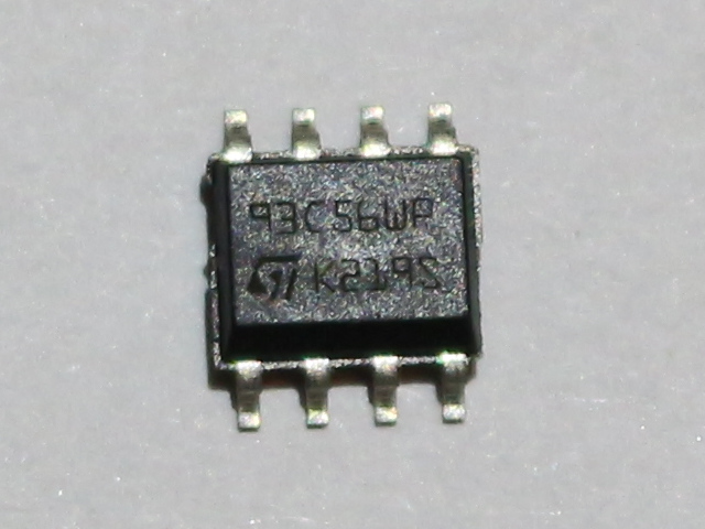
What I had to do, was to read contents of EEPROM, that I found on board, I am analyzing. It is quite obscure, as Google did not return anything useful (beside Taobao auctions). Fortunately I learned that chip it is connected to expect EEPROM from the 93Cx6 series. So, to not break anything, I bought few similar memory chips from usual source. In the meantime, I found that this thing talks Microwire protocol, which is quite similar, but not identical to SPI. This means that flashrom is not an option here. It is however similar enough to SPI that some people were successful in talking to these EEPROMs on SPI bus. Unfortunately, I did not have any device that was confirmed successful and I did not want to experiment with low chance of success. Luckily for me, there is simple Arduino library, that bit-bangs the protocol. I am not a big fan of Arduino, but I have few Digispark boards, so I decided to give it a try. Obviously, the fact that this post appeared means, I was successful. Nevertheless, it was not that easy. At least for me, so I share my experience, just in case someone have similar problem. Enough of this, let’s read (and write, if you want) Microwire 93C56 EEPROM with Arduino sketch and Digispark board, via USB virtual serial port. Because, why not? 🙂
Hardware
From the hardware point of view, it seems to be quite easy task. We need the same four signals as with SPI, but their names are a bit different. So, there is CS – chip select with the difference that it is active high, unlike SPI’s chip select or slave select. Then, there is CLK, which is simply a clock. And biggest differences are data lines, which are called DI – data in – and DO – data out – equivalents to MOSI and MISO in SPI. This means that we need 4 digital data lines in order to be able to communicate.
At first sight, this means Digispark is more than enough in terms of available pins. However, if we take deeper look at its implementation, we will see that indeed, there are 6 digital pins. However two of them are connected to USB D+ and D- signal lines. This means, that we can only utilize them, if we don’t need USB. And my plan is to transfer data through USB to PC (or actually Raspberry Pi). What’s worse, pin number 5 is by default reset pin. It is pulled up to VCC all the time, when uC is powered on. So, in fact we are left with 3 spare pins. Now, if you are clever, you might think, that you don’t need CS. Or actually, that you can tie it to VCC permanently. There is only one problem with that. CS line must be pulled low after each command. So, having it constantly pulled up should result in first and only first command being executed. Provided this is read command. Writes execute only on falling edge of CS. And even for reading, most likely, you would need to reset Digispark the same amount of times, as the number of words you want to read. And remember, where you stopped last time.
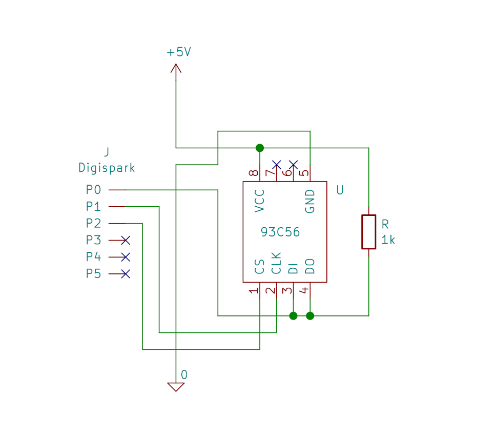
So, do we need 4 lines? Or can we have 3? The answer is, we can use only 3. By connecting DI and DO together, making some additional circuitry and adapting program to the changes. At first, let’s look at the circuit, we need to build:
Software
Library
Now, from the software, or to be precise, library perspective, it looks much more complicated. Maybe there is other way to achieve the same goal of communicating with EEPROM with DI and DO pins tied together. I’m not an expert. The method I will try to explain below is based on what my colleague suggested (thanks Marek!). Of course, I will most likely be wrong sometimes when explaining this, as I am not an expert in electronics, as I already wrote.
Throughout this tutorial, I will be basing on MicrowireEEPROM library, modified by me and available as a fork of original library. This one should be packed into zip file and installed in Arduino IDE, so we could use it in a sketch. Then, we will use this sketch as a base for handling Digispark-EEPROM connection and Digispark-PC connection via USB CDC, so PC will see Digispark as virtual serial port.
But let’s start with explanation of the changes I did on the library published by tim0s. First of all we have both signals – input and output on the same pin. This means we cannot configure it as output and then as input, as was done in original library. To help me explain what will be happening instead of that, let me show you one schematics from Microchip’s datasheet.
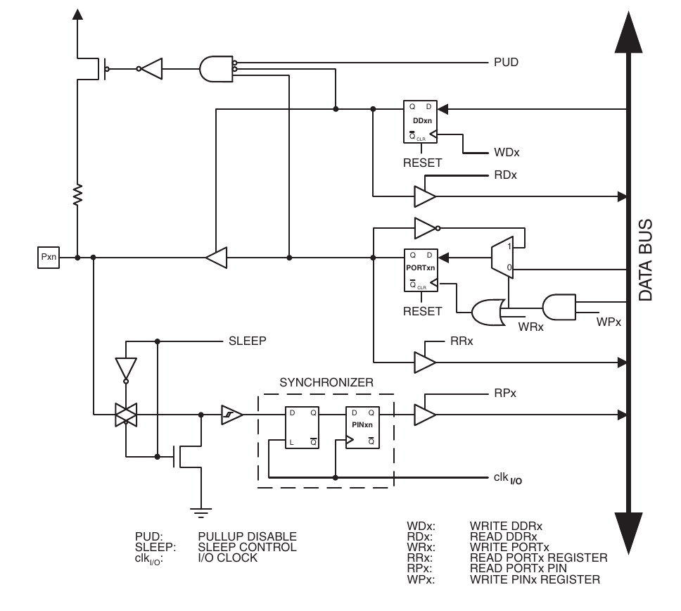
In the upper left corner of this schematics, there is a pull-up resistor. We are not using it, but we do something similar externally, as can be seen on the hardware schematics above. The result of this configuration is that data pin will always be a digital 1, whenever not connected to any other source of current. And what other source of current do we have here? The one that can be switched on or off by WDx bit on the schematics. WDx is direction of a pin. In can be either input (0) or output (1). In case, where this is input, the situation is quite simple, as we have only pull-up connected. For output, we connect the whole system with WPx on the end, so now the final state depends on the value, written into port register. We want it to be low in such case, as we have 1 “by default”. This not quite obvious system allows us to set output state of the pin with direction bit, instead of a bit in port register. Now the truth table is as follows:
| DDRx | Output |
|---|---|
| 0 | 1 |
| 1 | 0 |
Not exactly intuitive, but works. Now the input part.
This turned out to be a bit tricky, too. During the timeframe, when we are reading bits from EEPROM, we have to make sure that we are not set to zero at the same time, means that direction bit is set to 0 – input. So, what is tricky here? It turned out that MicrowireEEPROM library always does both write and read of a bit at the same time. This seems to be superfluous to me, as we can’t have an input and output bit transmitted at the same time. This sounds like an implementation of SPI. So, author decided to transmit zeros while reading data from memory chip. Bad idea for our case. This caused only zeros to be read, as attiny was pulling the line down. Changing it to always transmit 0xffff in such case, solved the problem.
That’s it from library point of view. You can view complete set of my patches on Github, if you are curious.
Program
Finally, with library ready to go, we can start to prepare a program that will use it to read the complete dump of a chip. You can find complete Arduino sketch as a gist. I will try to explain it a bit here. First step is to initialize MicrowireEEPROM library class. For that we need to know few parameters: pins for DI/DO, CS and CLK, Width of data and address words and speed at which we would like to transmit.
For the interface pins, it is quite easy. Pin numbering on Digispark is exactly the same as in Arduino, so all we have to do is to put right values. Data bus has width of 16 bits, unless you have ORG pin on your EEPROM and you connected it to ground. So, I assume, 16 is used. With address bits, it is a bit more complicated. If you know the chip manufacturer and have access to datasheet, you can check it there. Otherwise, you have to guess or sniff communications to check what number of bits memory user is transmitting. In my case this was 8, as I have 93C56 manufactured by ST. But I also have unidentified device that uses this protocol and have 9-bit address.
Last thing is clock speed. Or actually period of a clock signal. It is put in microseconds. I used 200 us, which is for clock of speed 5 kHz. This speed for sure has no problem with pull-up resistor and Digispark easily drives the pin at desired speed. I guess increasing the speed a bit (meaning decreasing the period) would also work and be slightly faster. But remember, that we read EEPROM of sizes lower than 1 KiB, so you probably do not care about the speed that much.
What I do next is to initialize USB serial device and wait for user input, so I would be able to read data with a program that connects to virtual serial port after it is registered in host system. Finally I read all the data sequentially and push them to serial port in hex format, so I can either handle them with script, or read with e.g. minicom.
Results
And that’s it. We have working EEPROM dumping tool. For writing, we simply need to use write command. I already did this for testing and it works. Maybe the missing part is how to get the desired memory contents from USB. But this I leave as an exercise for those readers that need it.
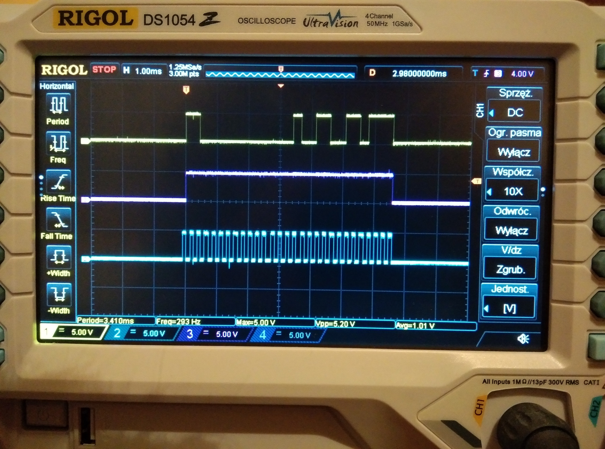
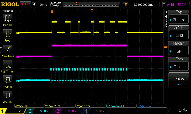
Last but not least, below are some photos, I took while debugging my setup with oscilloscope. Could be useful in case of any problems with your setup.