NOTE: This post was imported from my previous blog – v3l0c1r4pt0r.tk. It was originally published on 1st November 2013.
This post is the second part of the Instructable mentioned on the previous post. That’s tutorial on how to make simple FM radio using GRC. That task is in my opinion the simplest project that can be made using GRC so it’s in fact beginners guide to GNU Radio which is really capable software. I hope that it is only the first my project using that software.
It isn’t hard to find GRC projects that implements FM radio functionality, that’s a fact. But when it comes to reproduce them so they are working just like SDR# you’d realize it’s a bit harder task. At least I did. I found about a three such projects but there was never any included project file and the only materials was video or pictures. I admit the video has pretty good explanation but it still wasn’t enough. The rest was even worse. They were only blog posts with few screen shots and short description. So finally to reproduce functionality of SDR#’s FM radio I had to think on my own. And after few hours I did what I tried to do.
A bit of theory
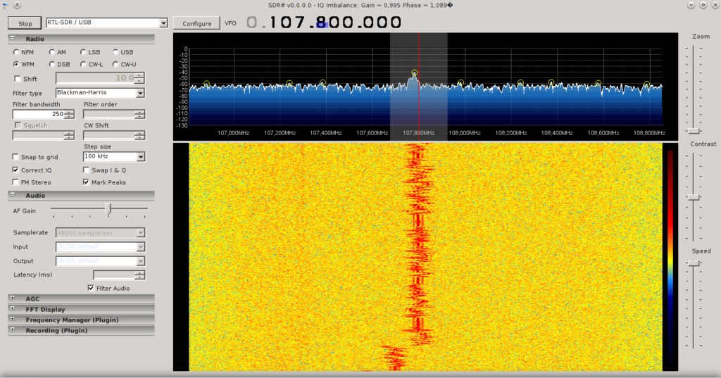
But let’s start at the beginning. The first thing that you need to do to start creating your own FM receiver using GRC is to find FM station that can be received without disruptions so you can check if your program works as well as i.e. SDR#. It can be done with help of SDR# and when you found one you are ready to learn some theory about FM signal processing. In fact it could be omitted, but in my opinion it is better to know a bit. I personally am not any specialist in radio theory so it will be really simple and I might be wrong somewhere so if you find any mistake in that what I will write here just let me know in comments.
The simplest FM radio consists of few elements:
- signal source – in our case it would be RTL-SDR dongle
- low pass filter
- WBFM demodulator
- audio output – your PC’s sound card
There can be few other elements depending on input and output sample rate, if it will be possible to match them using only above elements there won’t be any other. So our task will be getting signal using RTL-SDR, passing it through low pass filter and FM demodulator and outputting on PC’s sound card. Meanwhile we will also need to match the sample rate of the input to the one of the output (2 MHz in to 48 KHz out). All elements of this circuit can be found by writing part of its name while list on the right is selected. Element’s names are the ones used as section header below.
RTL-SDR source
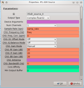
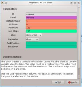
Our signal input. We need to set its sample rate to 2M. It can be done by editing samp_rate variable and setting its value to 2e6. We need also to set the frequency of the station we want to receive. It is good practice to add every value that might be changed in the future as standalone variable. This can be done by adding Variable block from Variables category or, if you want to have possibility to edit it during the runtime block named WX GUI Slider or WX GUI Text Box and then just writing variable name as value in block’s properties.
Rational Resampler
Now we need to convert sample rate from 2M (samp_rate) to 500K which I realized is the best value for low pass filter’s input rate. To do that we need to add another variable, named i.e. quadrature, set its value to 500e3 (means: 500K). With that we need to add rational resampler’s block and set its decimation value to int(samp_rate/quadrature). Of course its input on the schematic should be connected to output of RTL-SDR Source (can be achieved by clicking on blue out on one block and then blue in on another).
Low Pass Filter
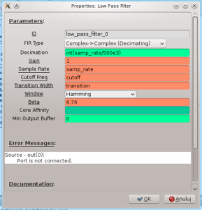
The next step is to filter out frequencies other than the one we centered in th previous step. In that task we will use a low pass filter block. We here set cutoff frequency to 100e3. This is because that’s standard band’s width. I don’t know what correct value for transition width should be, but trying to change that I found that the higher value the better so it’s finally set to 1M. Obviously it should be connected to resampler’s output.
WBFM Receive
Now we could do the nearly final and the most important step: placing the FM demodulator. In my case its quadrature rate equals 500k (that’s the same value as before so I set this to the value of quadrature variable). I don’t know if it could be changed to something else so if you are not sure just leave it as is. In that setting it should work.
Next Rational Resampler and Multiply Const
These elements’ job is to match the signal’s rate to the one supported by sound card and provide volume regulation. At first we need to convert rate from 500k to 48k so we need to decimate by 500 and then multiply by 48. In the second block we set const to volume. Now we can create variable or place WX GUI Slider with variable name set to volume. As you can see here color of WBFM demodulator is different than rational resampler’s and multiplier’s in and out. To change that you need to select them and use up and down arrows on your keyboard.
Audio Sink
That one’s function is to output signal on our sound card. Now its only required to edit its rate and choose 48k from a drop down list and that’s it! If you don’t have that option just choose the biggest value and edit value in rational resampler and it should work. Now you should be able to execute your program and test if it works. To hear anything it will probably be required to increase volume to about 50.
Finally: some links
If you don’t know how some part has been done or what value should have a particular variable below you can download projects that I’ve made first learning to use GRC myself and then preparing this tutorial. There is one project presented here and one made earlier.


