Skip to content

re-ws.pl

ReverseEngineering WorkStation

  • Home
  • Tutorials
  • Random
  • About

Category: Tutorials

[Import]Hacking Vasco translator through binary SMS

Posted on September 4, 2017 - September 7, 2017 by Kamil (aka. v3l0c1r4pt0r)

NOTE: This post was imported from my previous blog – v3l0c1r4pt0r.tk. It was originally published on 18th February 2017.

Recently I was asked to configure internet browser on a thing called Vasco Translator Premium 7″. The device looks exactly like many of the low-end Android tablets from China. And it happens to be one. The problem is that is was locked to used the only allowed application which is the translator. It has some minor functions like camera and it seems that was a mistake of its authors. They used default Android app as Camera and Gallery applications (and forgot to lock send message button in the latter 🙂 ).

At first I have to highlight the fact, this is not the full unlock or root of the device, but the fact of ease of the process allows me to suppose that rooting the thing should not be too difficult, too. Our goal here is to open up the web browser. Because as it seems the software below the shitty overlay is ordinary Android with all the apps on its place. And how useful might be the tablet without internet browser?

Prerequisites

The tool we will use to do the trick is good ol’ WAP Push protocol. For some reason in newer Android devices this dinosaur has been revived and supported out of the box. The goal is to send such message to our locked device, and since the gallery app mentioned above allows to escape to Messaging app, read it on it. This is probably the hardest part of the process. And possibly may require to buy some additional hardware (if you have access to any service, you know is sending WAP Push, you can use it and skip this part).

And that hardware is a GSM modem. It is highly possible that you already have one that can be used. The thing we will need is the possibility to send SMS through AT commands. Many Android phones allows that, at least if they are rooted, probably LTE/3G modems can do that too (not checked that personally). Ok, since the procedure to get access to AT interface is completely different for any device you can get, I have to leave you alone with getting used to that. After some time, you will probably end up in minicom or some similar program and parameters like 115200/8N1 or 9600/8N1. In my case (Android with Qualcomm processor) it is /dev/smd11 and params are 115200/8N1. Now you could type AT to check if the device you found is really an AT modem (should respond with OK) and AT+SCA? to check your SMS center address. You should be able to recognize it or Google it to check if it really belongs to your mobile operator.

Crafting SMS

Now, since we have all the tools, we can start crafting SMS. I will omit many details here since just general description of PDU format would take whole article and complete one is more than 100 pages long. The only part you need to know about is destination address. This will be the phone number of your device. Trailer of the message is WAP Push payload, which to be described will need another 100 or so pages, so skip it. As a remark, there is some program called wbxml2xml/xml2wbxml that allows to read/write the message. In our case, we want to enforce the device to visit Google.com, so this will be the address of WAP bookmark.


Ok, so on the picture above, thing we are interested in are [dest_addr] and [dest_len]. The first encodes telephone number “+37201234567” (note lack of ‘+’ sign), the second its length (as number of digits, 0x0b == 11). The number of your device should be placed here and you could move on to next section.

Or you can try customizing the payload. The important thing here is marked as [WBXML] and can be crafted with program mentioned before. After changing this, adjustment of [ud_len] value to number of bytes in payload (those after the length) is required.

Sending SMS

Since we already have modem, we need to type AT command to initiate message sending. But before that, we need to ensure that we are in binary mode. Type AT+CMGF? and, if value is other than zero, AT+CMGF=0. Now start sending with:

AT+CMGS=55

Where 55 is length of payload in bytes, but without SMSC header (one byte at the beginning). Modem should respond with > prompt, where SMS could be typed.

0041000b917302214365f700042a0605040b8423f0ea0601ae03056a0045c60c03676f6f676c652e636f6d00080103476f6f676c65000101

And after that press CTRL-Z (^Z) in your terminal. This should send SUB (substitute) to modem. It is important not to use any characters in between, like spaces and ENTER. After about a second, you should see that sending was successful and no error was returned.

Receiving and opening

Now, if you have your translator turned on, you should hear that new message was received, but nothing appeared on screen. That is ok. The rest of the procedure is shown on video below:

Postscriptum

After another few minutes of playing with the device I found another method of opening the browser and it is way faster than what was described below. But the first one was much more entertaining for me and is showing one of the many places where serious bugs could be found – forgotten technologies, still being implemented, possibly used, but with lack of knowledge about details in general public.

You can see the other method on video below, and possibly it is the one you want to use.

Posted in TutorialsTagged Android, English, hacking, Hayes modem, SMS, WAP1 Comment

[Import]Understanding JCOP: memory dump

Posted on September 4, 2017 - September 10, 2017 by Kamil (aka. v3l0c1r4pt0r)

NOTE: This post was imported from my previous blog – v3l0c1r4pt0r.tk. It was originally published on 8th February 2017.

Some time ago I was struggling with JCOP smart card. The one I received as it turned out was not pre-personalized, which means some interesting features (like setting encryption keys and PIN) was still unlocked. Because documentation and all the usual helpers (StackOverflow) were not very useful (well, ok, there was no publicly available documentation at all), I started very deep search on Google, which finished with full success. I was able to make dump of whole memory available during pre-personalization.

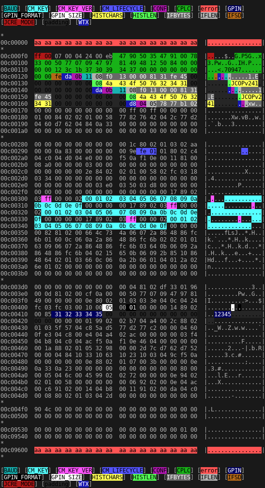
Since it is not something that could be found online, here you have screenshot of it, colored a bit with help of my hdcb program. Without documentation it might not be very useful, but in some emergency situation, maybe somebody will need it.

JCOP memory dump made at the very beginning of pre-personalization

Small explanation: first address, I was able to read was 0xC000F0, first address with read error after configuration area was 0xC09600. I know that, despite of lack of privileges some data is placed there.

There are three configurations: cold start (0xc00123-0xc00145), warm start (0xc00146-0xc00168) and contactless (0xc00169-at least 0xc0016f). Description of coding of the individual fields is outside of the scope of this article. I hope, I will describe them in future.

Next time, I will try to describe the process of pre-personalization, that is making not pre-personalized card, easy to get from usual sources of cheap electronics, able to receive and run applets.

Update: Next part of this tutorial can be found under this link.

Posted in Tutorials, Understanding JCOPTagged electronics, English, hacking, hardware, JavaCard, JCOP, Reverse Engineering, smart cardLeave a comment

[Import]Wget with SSL/TLS support for Android

Posted on September 4, 2017 - September 7, 2017 by Kamil (aka. v3l0c1r4pt0r)

NOTE: This post was imported from my previous blog – v3l0c1r4pt0r.tk. It was originally published on 12th September 2016.

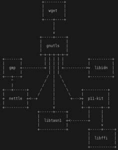
wget dependency tree

Lately I have tried to download some file from a website to my Android smartphone. Simple thing, yeah? Well, not really. Unfortunately mobile browser developers removed many features from their mobile distributions. One of them is a possibility of downloading random page to disk as is. Instead (this is the case at least with Mozilla’s product) they are forcing “Download as PDF” feature. I had a bit of luck, because the file I was trying to download was MP4 movie, which is downloadable, maybe not in an intuitive way, but it is. But before I have found that feature hidden in a player’s context menu, I tried another solution – wget. Since I am great fan of terminals, I have busybox installed on my phone. Those of you, who know what exactly is busybox should know that this is set of lightweight variants of most standard UNIX tools. So, if they are lightweight, they had to cut some part of tool functionality, right? And in case of my busybox’s wget, they cut HTTPS support. And today, it is more likely to encounter site which is only HTTPS than one that is only HTTP, at least when talking about popular sites. So I had to get my own distribution of wget, that will not be such constrained one.

Not to get you bored too much, here you can find binary distribution of what I achieved to compile. It was compiled for ARMv7 platform using NDKr12b and API level 24 (Nougat), so it will probably not work on most of current Android phones, but if you read later, it is probably working on your device or even is outdated. If you are interested in recompiling binaries yourself, you can find detailed how-to in the next part of this article.

Dependencies

Before compiling wget itself, you have to have whole bunch of its dependencies. But at first, you of course need Android compiler. It is distributed as part of NDK and I won’t describe its installation here. Sources of every program compiled here can be grabbed from its official sites (list at the end of this post). The only exception is libtasn1, which required few hacks to be done to make it compile with Android bionic libc. Its source, ported to Android can be get from my github repo.

Let’s start with programs that does not depend on anything. For all projects, the procedure is more or less the same and can be described with simplified bash script:

tar -zxvf program-1.00.tar.gz
mkdir build
mkdir install
cd build
CC=arm-linux-androideabi-gcc AR=arm-linux-androideabi-ar RANLIB=arm-linux-androideabi-ranlib CFLAGS=-pie \
    ../program-1.00/configure --host=arm-linux --prefix=/data/local/root
make
make install DESTDIR=$(dirname `pwd`)/install/
cd ../install
tar -zcvf program.tar.gz *

gmp, libidn and libffi

For these three programs, the procedure above should work without any modification.

nettle

Since nettle depends on gmp, it has to be configured with paths to gmp binaries and headers in its CFLAGS and LDFLAGS variables. They should look like this:

CFLAGS="-pie -I`pwd`/../../gmp/install/data/local/root/include"
LDFLAGS="-L`pwd`/../../gmp/install/data/local/root/lib"

when invoking configure script.

libtasn1

This was the hardest part for me, but should go smoothly now. Script below should do the work correctly:

git clone git@github.com:v3l0c1r4pt0r/android_external_libtasn1.git
mkdir build
mkdir install
cd build
CC=arm-linux-androideabi-gcc AR=arm-linux-androideabi-ar RANLIB=arm-linux-androideabi-ranlib CFLAGS=-pie \
    ../libtasn1/configure --host=arm-linux --prefix=/data/local/root --disable-doc
make
make install DESTDIR=$(dirname `pwd`)/install/
cd ../install
tar -zcvf libtasn1.tar.gz

p11-kit

This is the last dependency of gnutls which is the only, but very important dependency of wget. Just embedding libtasn1 and libffi should do the job well.

CFLAGS="-pie -I`pwd`/../../libtasn1/install/data/local/root/include"
LDFLAGS="-L`pwd`/../../libtasn1/install/data/local/root/lib -L`pwd`/../../libffi/install/data/local/root/lib"

Notice that libffi has no headers, so we add it just to CFLAGS here!

gnutls

This one was more complicated than the rest. As I mentioned above, it is very important to wget functionality. However wget’s dependency on it could probably be turned off, we would not have TLS support then. When compiling it I had some problems that seemed to be serious. There were a few errors while making it, so I had to call make twice and even though it failed. Despite that it seem to work after make install, which obviously failed too. In my case following script did the job:

mkdir build
mkdir install
cd build
CC=arm-linux-androideabi-gcc AR=arm-linux-androideabi-ar RANLIB=arm-linux-androideabi-ranlib \
    CFLAGS="-pie -I`pwd`/../../gmp/install/data/local/root/include -I`pwd`/../../nettle/install/data/local/root/include -I`pwd`/../../libtasn1/install/data/local/root/include -I`pwd`/../../libidn/install/data/local/root/include -I`pwd`/../../p11-kit/install/data/local/root/include" \
    LDFLAGS="-L`pwd`/../../gmp/install/data/local/root/lib -L`pwd`/../../nettle/install/data/local/root/lib -L`pwd`/../../libtasn1/install/data/local/root/lib -L`pwd`/../../libidn/install/data/local/root/lib -L`pwd`/../../p11-kit/install/data/local/root/lib" \
    ../gnutls-3.4.9/configure --host=arm-linux --prefix=/data/local/root --disable-cxx --disable-tools
make || make
make install DESTDIR=$(dirname `pwd`)/install/ || true
cd ../install
tar -zcvf file.tar.gz *

Compilation

Since we should now have all dependencies compiled, we can try compiling wget itself. The procedure here is the same as with dependencies. We just have to pass path to gnutls. And then standard configure, make, make install should work. However if your NDK installation is fairly new and you were not hacking it before, you most likely don’t have <sys/fcntl.h> header and make should complain about that. Luckily Android itself have this header present, but for reason unknown it is kept in include directory directly. To make wget, and any other program that uses it, compile you can just point “sys/” instance to <fcntl.h> with symlink or do something like that:

echo "#include <fcntl.h>" > $TOOLCHAIN/sysroot/usr/include/sys/fcntl.h

where $TOOLCHAIN/sysroot is path at which you have your headers placed. Depending on tutorial you were using for making it work it may have different structure.

Installation

All commands I presented above implies that you have your custom-compiled binaries in “/data/local/root”. I made it that way to have clear separation between default and busybox binaries. If you want to have them somewhere else, you should pass it to configure scripts of all programs you are compiling. After successful compilation of all tools, I have made single tarball containing all compilation output (this file’s link was placed above). Its content can be installed into Android by typing

tar -zxvf wget-with-deps.tar.gz -C/

using adb shell or terminal emulator.

Sources

Below you can find links to sources of all programs nedded to follow this tutorial.

  • wget
  • gnutls
  • gmp
  • nettle
  • libtasn1
  • libidn
  • p11-kit
  • libffi

Posted in TutorialsTagged Android, English, LinuxLeave a comment

[Import]CP210x (USB to TTL adapter) for Android devices

Posted on September 4, 2017 - June 13, 2018 by Kamil (aka. v3l0c1r4pt0r)

NOTE: This post was imported from my previous blog – v3l0c1r4pt0r.tk. It was originally published on 22nd August 2014.

Few days ago, while searching for something interesting I can do with my Android phone I found out that Sony is publishing kernel source of all their (and old SE ones too) ROMs. Beside hacking the kernel itself I was wondering if it is possible to compile additional kernel modules (stock ROM provides only internal WiFi module’s drivers). Well.. it was. The first one I tried was driver of my cheap, Chinese USB to serial adapter based on CP2102 chip.

Prerequisites

  • kernel source – it is important to be the same kernel as the one working on your device. Otherwise it would probably be necessary to boot your system with kernel compiled with source you have and it will not be described in this tutorial. The reason it is important is that between kernel version compatibility is not guaranteed. Different configuration could mess with functionality too (but not tried myself). I have Sony Ericsson device so I downloaded from its official repository.
  • cross-compiler – while compiling programs for Android you definitely should get special version of a compiler because Android is different than usual Linux box so compiler options are different too. The easiest way is to download official NDK which has built-in compilers and easy-to-use script to make standalone toolchain out of them. Same toolchain should also work as compiler for kernel but I haven’t tested it myself. In case it didn’t there is very powerful tool for making your own toolchain for any platform supported by GCC so in practice any you can imagine called crosstool-ng (on Arch available on AUR).
  • uucp source code

Kernel module

We will start with a kernel module. First of all we will unpack our kernel. In case of SE kernel need to be uncompressed and then unpacked so I did:

bzcat 4_1_B_0_431_tar.bz2 | tar -xv
cd kernel

And changed dir to kernel. Next thing I had to do was patching Makefile, because it complained about unused variables. If you are using Sony or SE kernel you probably need to do it too. If so create file named Makefile.patch with your favorite editor, i.e.

vim Makefile.patch

and paste following content:

--- Makefile  2012-05-25 12:07:05.000000000 +0200
+++ Makefile.new  2014-08-20 21:16:50.642703198 +0200
@@ -342,7 +342,6 @@
 KBUILD_CPPFLAGS := -D__KERNEL__

 KBUILD_CFLAGS   := -Wall -Wundef -Wstrict-prototypes -Wno-trigraphs \
-		   -Werror \
 		   -fno-strict-aliasing -fno-common \
 		    -Werror-implicit-function-declaration \
 		    -Wno-format-security \

Now you can patch it with:

patch Makefile < Makefile.patch

Then we can start the compilation process which should end in a second. I assume you have working toolchain in your $PATH and it is prefixed with arm-unknown-eabi- (arm-unknown-eabi-gcc, etc.). If its name is different change all occurrences of arm-unknown-eabi- below.

make mrproper
ARCH=arm CROSS_COMPILE=arm-unknown-eabi- make semc_iyokan_defconfig
ARCH=arm CROSS_COMPILE=arm-unknown-eabi- make prepare
ARCH=arm CROSS_COMPILE=arm-unknown-eabi- make modules_prepare
ARCH=arm CROSS_COMPILE=arm-unknown-eabi- make modules SUBDIRS=drivers/usb/serial CONFIG_USB_SERIAL=m CONFIG_USB_SERIAL_CP210X=m

If everything worked you should have your module compiled in drivers/usb/serial directory. It is worth to note you could compile any other module the same way. It is only important to change SUBDIRS to your module location and ensure it is configured to be built by issuing make menuconfig or setting appropriate CONFIG-* variable to ‘m’.

Now you can copy modules to your devices. With adb it will be:

adb push drivers/usb/serial/usbserial.ko /mnt/sdcard/others
adb push drivers/usb/serial/cp210x.ko /mnt/sdcard/others

We have two modules to copy here since cp210x (and any other serial device driver) depends on usbserial and without it being already in kernel it would be impossible to insert cp210x and furthermore it will give you strange error message (tested :). So now, again with help of ADB, we can insert our modules.

adb shell
su
cd /mnt/sdcard/others
insmod ./usbserial.ko
insmod ./cp210x.ko

After that you can connect your device and device you compiled module for and test if it works. Serial adapters should create new device file in /dev and, at least with CP210x, it uses ttyUSB* name so you can list it with:

ls -l /dev/ttyUSB*

You can also read from your port as simply as by typing

cat /dev/ttyUSB0

Now after you connect some device talking UART you should see its output.

Program to easily control our port – cu and the rest of uucp package

Warning: in the following steps I assume that you have directories like /data/local/bin and /data/local/etc already on your device. As far as I remember there is only /data/local by default.

At first we need to unpack our source and create some useful directories. Then we will configure our script in build-uucp so we won’t get garbage in source directory and could easily clean things when something goes wrong.

tar -zxvf uucp-1.07.tar.gz
mkdir build-uucp
mkdir install-uucp
cd build-uucp/

Then we will patch our program so it will work on Android out of the box. If we omitted following patch it would be necessary to create configuration file, configure program to read it before work and whole bunch of similar fun. So it is easier to let him know where he could store his files now. You can obviously use the one you want to. If you stay with my config you won’t be able to start cu as normal user which is no problem because by default you won’t have permission to use serial terminal.

Now the procedure is the same as with previous patch. I assume you used policy.h.patch name and the content is:

--- policy.h  2003-05-29 08:08:45.000000000 +0200
+++ policy.h.new  2014-08-20 12:03:45.595405893 +0200
@@ -297,7 +297,7 @@
    systems the lock files are placed in /etc/locks.  On some they are
    placed in /usr/spool/locks.  On the NeXT they are placed in
    /usr/spool/uucp/LCK.  */
-/* #define LOCKDIR "/usr/spool/uucp" */
+#define LOCKDIR "/data/local/etc/spool/uucp"
 /* #define LOCKDIR "/etc/locks" */
 /* #define LOCKDIR "/usr/spool/locks" */
 /* #define LOCKDIR "/usr/spool/uucp/LCK" */
@@ -572,7 +572,7 @@
 /* The name of the default spool directory.  If HAVE_TAYLOR_CONFIG is
    set to 1, this may be overridden by the ``spool'' command in the
    configuration file.  */
-#define SPOOLDIR "/usr/spool/uucp"
+#define SPOOLDIR "/data/local/etc/spool/uucp"
 /* #define SPOOLDIR "/var/spool/uucp" */

 /* The name of the default public directory.  If HAVE_TAYLOR_CONFIG is
@@ -580,7 +580,7 @@
    configuration file.  Also, a particular system may be given a
    specific public directory by using the ``pubdir'' command in the
    system file.  */
-#define PUBDIR "/usr/spool/uucppublic"
+#define PUBDIR "/data/local/etc/spool/uucppublic"
 /* #define PUBDIR "/var/spool/uucppublic" */

 /* The default command path.  This is a space separated list of
@@ -644,21 +644,21 @@
 /* The default log file when using HAVE_TAYLOR_LOGGING.  When using
    HAVE_TAYLOR_CONFIG, this may be overridden by the ``logfile''
    command in the configuration file.  */
-#define LOGFILE "/usr/spool/uucp/Log"
+#define LOGFILE "/data/local/etc/spool/uucp/Log"
 /* #define LOGFILE "/var/spool/uucp/Log" */
 /* #define LOGFILE "/var/log/uucp/Log" */

 /* The default statistics file when using HAVE_TAYLOR_LOGGING.  When
    using HAVE_TAYLOR_CONFIG, this may be overridden by the
    ``statfile'' command in the configuration file.  */
-#define STATFILE "/usr/spool/uucp/Stats"
+#define STATFILE "/data/local/etc/spool/uucp/Stats"
 /* #define STATFILE "/var/spool/uucp/Stats" */
 /* #define STATFILE "/var/log/uucp/Stats" */

 /* The default debugging file when using HAVE_TAYLOR_LOGGING.  When
    using HAVE_TAYLOR_CONFIG, this may be overridden by the
    ``debugfile'' command in the configuration file.  */
-#define DEBUGFILE "/usr/spool/uucp/Debug"
+#define DEBUGFILE "/data/local/etc/spool/uucp/Debug"
 /* #define DEBUGFILE "/var/spool/uucp/Debug" */
 /* #define DEBUGFILE "/var/log/uucp/Debug" */

@@ -669,17 +669,17 @@
 /* The default log file when using HAVE_V2_LOGGING.  When using
    HAVE_TAYLOR_CONFIG, this may be overridden by the ``logfile''
    command in the configuration file.  */
-#define LOGFILE "/usr/spool/uucp/LOGFILE"
+#define LOGFILE "/data/local/etc/spool/uucp/LOGFILE"

 /* The default statistics file when using HAVE_V2_LOGGING.  When using
    HAVE_TAYLOR_CONFIG, this may be overridden by the ``statfile''
    command in the configuration file.  */
-#define STATFILE "/usr/spool/uucp/SYSLOG"
+#define STATFILE "/data/local/etc/spool/uucp/SYSLOG"

 /* The default debugging file when using HAVE_V2_LOGGING.  When using
    HAVE_TAYLOR_CONFIG, this may be overridden by the ``debugfile''
    command in the configuration file.  */
-#define DEBUGFILE "/usr/spool/uucp/DEBUG"
+#define DEBUGFILE "/data/local/etc/spool/uucp/DEBUG"

 #endif /* HAVE_V2_LOGGING */

@@ -692,16 +692,16 @@
    be replaced by the system name (if there is no appropriate system,
    "ANY" will be used).  No other '%' character may appear in the
    string.  */
-#define LOGFILE "/usr/spool/uucp/.Log/%s/%s"
+#define LOGFILE "/data/local/etc/spool/uucp/.Log/%s/%s"

 /* The default statistics file when using HAVE_HDB_LOGGING.  When using
    HAVE_TAYLOR_CONFIG, this may be overridden by the ``statfile''
    command in the configuration file.  */
-#define STATFILE "/usr/spool/uucp/.Admin/xferstats"
+#define STATFILE "/data/local/etc/spool/uucp/.Admin/xferstats"

 /* The default debugging file when using HAVE_HDB_LOGGING.  When using
    HAVE_TAYLOR_CONFIG, this may be overridden by the ``debugfile''
    command in the configuration file.  */
-#define DEBUGFILE "/usr/spool/uucp/.Admin/audit.local"
+#define DEBUGFILE "/data/local/etc/spool/uucp/.Admin/audit.local"

 #endif /* HAVE_HDB_LOGGING */

If you prefer I have it on my gist so you can just issue one command and get it. Then we are patching as usually:

patch ../uucp-1.07/policy.h < policy.h.patch

As mentioned above you can change path of uucp’s files by issuing the following (remember to escape every occurrence of slash with backslash, otherwise it will fail):

sed -i "s/\/data\/local\/etc/[your-path]/" ../uucp-1.07/policy.h

Now you are ready to compile. It can be done with following commands. Your compiler should have same name (at least if you use NDK’s compiler). It is important to note that I had to switch off HAVE_SYSCONF flag since it was causing ugly errors. In my case makescript couldn’t also find a rule to make ftw.o so I had to make it myself. If you have no trouble here, just omit the line after make.

CC=arm-linux-androideabi-gcc AR=arm-linux-androideabi-ar RANLIB=arm-linux-androideabi-ranlib \
../uucp-1.07/configure --prefix=`pwd`/../install-uucp/ --host=arm-linux-androideabi
sed -i "s/#define HAVE_SYSCONF 1/#define HAVE_SYSCONF 0/" config.h
make
cd unix; make ftw.o; cd ..; make
make install
adb push ../install-uucp/bin/cu /mnt/sdcard/others
adb shell
su
cp /mnt/sdcard/others/cu /data/local/bin/

Finally you can test the program with the following and you should be able to talk RS232 with just a phone/tablet!

cu -lttyUSB0 -s115200

where 115200 is the speed the device you connect to transmits.

BTW: uucp have few other tools and by following this tutorial you compiled them all so you can explore them on your own.

Posted in TutorialsTagged Android, English, Linux, tty, UART, Xperia ProLeave a comment

[Import]How to bypass Secure Download Manager while downloading from Dreamspark

Posted on September 4, 2017 - December 11, 2017 by Kamil (aka. v3l0c1r4pt0r)

NOTE: This post was imported from my previous blog – v3l0c1r4pt0r.tk. It was originally published on 1st June 2014.

NOTE2: As people are reporting, THIS METHOD DOES NOT WORK anymore. Also I don’t have access to Imagine, so I would not be able to provide any help. Therefore, this article is left only for historic purposes, or for those that have some SDC files downloaded, when it was still valid and have valid decryption keys.

About a month or so ago I had an urgent need to download a copy of Microsoft Windows from Dreamspark. Unfortunately I haven’t Windows installed then so had to do this using Linux. After successful transaction I was given a link to SDX file and program called SDM. It looked that it would be easy. But it wasn’t. Program that I was encouraged to download was archive with .pkg extension. As I discovered few minutes later it was OS X application package. So the next step was to try to download Windows version and try to execute it with help of Wine. It failed. Then I tried to find some tips on the Net. I found a few other people having the same problem. Some of them could download using Wine and some not. For me there was only one solution: do it myself. As you probably guessed that way was a (almost) full success.

Solution

If you already have SDC file please do not skip since you probably still don’t have a key needed to unpack the file. The first step is to open SDX file in your favorite text editor. You will see a link. Open it in a web browser. Now you need to get to page source. The way it can be done depends on your web browser. Now we need to find few strange values in the code. The easiest way to achieve this is to search for keyword ‘edv*’ where * is the number of file you want to download counting from 1 (they are on ‘Items’ list on page you opened). Now you need to copy somewhere values of the following variables: ‘oiopu*’, ‘oiop*’, ‘fileID*’ (*-see above). The last one we need is ‘dlSelect*’ but for that one you need to search cause it is in a different place. Now you can build URL that will let you to file containing two interesting values: file URL and decryption string. This URL’s format is:

http://[SDXdomain]/WebStore/Account/SDMAuthorize.ashx?oiopu=[oiopu]&f=[fileID]&oiop=[oiop]&dl=[dlSelect]

Now you should see XML file that looks similar to this:

<information>
 <oiopua>01234abcd-0123-4567-890a-0123456789ab</oiopua>
 <edv>0123456789^^0123456789QwErTyUiOpAsDfGhJkLzXc0123456789QwErTyUiOpAsDfGhJkLzXc12345678</edv>
 <linkAvailable>1</linkAvailable>
 <errorTextKey/>
 <invokeExternalDownload>0</invokeExternalDownload>
 <fileUrl><![CDATA[http://software.dreamspark.com/dreamspark/ENGLISH/SDCfileName.sdc]]></fileUrl>
</information>

The last step here will be downloading file from fileUrl and saving edv value in file. The important thing is that the file with a key should be named exactly as SDC file with addition of ‘.key’ suffix.

Update:

I’ve just discovered that things are getting a bit different when the file size exceeds 2.0 GB. In that case Dreamspark is splitting file in two or more files. That situation could be easily recognized, because sdc file name’s suffix is: ‘.01.sdc’. In that case you need to try to download file which URL differs by only that one digit, ie. ‘.01.sdc’, ‘.02.sdc’, ‘.03.sdc’. When you encounter last file it should have smaller size than the rest and incrementing that number by one should give you BlobNotFound error.

After downloading all the files they just need to be joined into one. It can be easily achieved with dd, ie.

dd if=pl_windows_7_professional_with_sp1_x64_dvd_u_676944.02.sdc >> pl_windows_7_professional_with_sp1_x64_dvd_u_676944.01.sdc

and then optionally

dd if=pl_windows_7_professional_with_sp1_x64_dvd_u_676944.03.sdc >> pl_windows_7_professional_with_sp1_x64_dvd_u_676944.01.sdc

After that you will get sdc file prepared to unpack.

Unpacking SDC

Now since you have SDC file you can start unpacking it. The previous part was, at least for me, very easy. The problem started when I tried to discover how the file is stored in that container. But don’t worry, I’ve written simple program to do it for you. As of now (1st June) it is still in really early alpha stage and have lot of constraints. It is able to unpack containers that contains only one file packed, doesn’t create any directories, cannot verify file’s checksum and probably few other problems I don’t remember or don’t know about.

If you were searching a bit in the Internet, you probably found out that someone cracked that container in the past. Unfortunately Microsoft changed format since then. It is also possible that in response to this article it will be changed again. To make it a bit harder for them to block my software I’m publishing source code on github and after the process of reverse engineering is finished will write second article describing how things works under the hood and describe sdc file format.

But let’s get back to unpacking. Now you need to download xSDM from github. The newest version can be downloaded by typing

git clone https://github.com/v3l0c1r4pt0r/xSDM.git

in your terminal (of course you need to have git installed). Nevertheless I advice you to download newest tagged release. You can do this by clicking on releases on project page and then choosing the one on the top (or first beta/stable if any) and clicking on “tar.gz”. tar.gz can be unpacked by typing

tar -zxvf xSDM-[tag-name].tar.gz

into console. Then get into xSDM directory by typing

cd xSDM

(or your release directory) and compile the program by standard

./configure
make
make install

where installation is optional. Now to unpack your file you just need to type

src/xsdm [path-to-your-sdc-file]

And that’s it, you should now be able to open file you downloaded. As mentioned above the program is in very early alpha so I cannot guarantee that it will work in any case. If you will encounter any problems feel free to open issue on project page at github.

Posted in TutorialsTagged Dreamspark, English, Linux, Reverse Engineering, SDC, SDM, Windows44 Comments

[Import]Graphic LCD based on ST7565 chip under Raspberry Pi

Posted on September 4, 2017 - September 7, 2017 by Kamil (aka. v3l0c1r4pt0r)

NOTE: This post was imported from my previous blog – v3l0c1r4pt0r.tk. It was originally published on 25th December 2013.

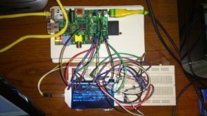
Hi, today I’d like to show you how to connect and use gLCD module with Raspberry Pi as host. The display I have is only bare display without any board not like the one in Adafruit’s offer. It can be powered by 3V3 Raspberry but the display itself needs a bit more power so we will need a few capacitors to build a circuit for that purpose. It will also make the connection a bit complicated (can be seen in the photo on the right). Nevertheless I think that the process is still rather easy.

Overview

Connected display

As far as I know ST7565 based displays can be connected on two ways: parallel and serial. In case of serial connection, which I used to save few GPIO’s, it is possible to program it using SPI or just only GPIO’s. The display that I have is a bit different than most of the others because it has external backlight, which is additionally single LED so it is very power-saving (15mA). The only problem with that backlight was that the vendor didn’t told anything about parameters of that diode so I needed to figure it out myself.. The second problem while connecting the display itself might be amount of cables that need to be connected when using breadboard. Despite these two facts the whole process should be easy.

Physical connections

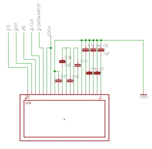
Connection scheme

As said before the only step that may be a bit complicated is connecting so called step-up voltage circuit, made of 4 capacitors. The capacitors that we will use are 1uF electrolytic caps. Beside that we need to use another 5 caps (same as before) to connect parallel inputs to ground. So in sum we need 9 of them. Now we only need to connect VDD to 3V3 pin on Raspberry, ground from the schematic on the right with GND pin, SDATA to SMOSI on Pi, SCLK to SCLK and A0, RST and CS to any free GPIO. It is good to remember their numbers cause we will need it in a moment 🙂 It is important to use numbers used by Linux kernel, not wiringPi which has its own names. At last we need to connect the backlight. As said I have ECO backlight so I had to connect mine using 10 Ohm resistor. You can connect it to 3V3 or if you like to have control during runtime use GPIO, just like any other LED.

Configuring the program

Now I have to mention something about a program itself, because depending on how your vendor implemented the things your display will almost surely need a bit different settings. General procedure will look the same on every ST7565-based display. Main differences will be on particular commands during setup procedure.

 
uint8_t init() 
{ 
  if (!bcm2835_init()) { 
    return 0; 
  } 
  bcm2835_gpio_fsel(LCD_BACK,BCM2835_GPIO_FSEL_OUTP);   //backlight 
  bcm2835_gpio_fsel(LCD_A0,BCM2835_GPIO_FSEL_OUTP);   //A0 
  bcm2835_gpio_fsel(LCD_RST,BCM2835_GPIO_FSEL_OUTP);    //RST 
  bcm2835_gpio_fsel(LCD_CS,BCM2835_GPIO_FSEL_OUTP);   //CS 
  bcm2835_gpio_write(LCD_CS,HIGH);        //set CS to high to indicate the bus as free 
  bcm2835_gpio_write(LCD_RST,LOW); 
  bcm2835_delayMicroseconds(1); 
  bcm2835_gpio_write(LCD_RST,HIGH);       //hardware reset 
  //setup SPI 
  bcm2835_spi_begin(); 
  bcm2835_spi_chipSelect(BCM2835_SPI_CS_NONE);      //manual CS control 
  bcm2835_spi_setClockDivider(BCM2835_SPI_CLOCK_DIVIDER_4); //set speed to 62.5MHz (fastest supported) 
 
  int i; 
  bcm2835_gpio_write(LCD_CS,LOW); 
  for(i = 0; i < sizeof(initcmd)/sizeof(uint8_t); i++) 
    transfer(initcmd[i],0); 
  bcm2835_gpio_write(LCD_CS,HIGH); 
  bcm2835_gpio_write(LCD_BACK,HIGH);        //turn backlight on 
 
  return 1; 
} 

I think that the code above should be generally clear. The most important for us is for loop that is executing every byte from initcmd array. Its content will look like that:

const uint8_t initcmd[] =
{
  0xa1,             //screen orientation
  0x41,             //set starting line
  0xc0,             //page count direction
  0xa3,             //1/7 bias
  0x2c,             //vc
  0x2e,             //vc+vr
  0x2f,             //vc+vr+vf
  0x24,             //voltage regulator (0x20-0x27)
  0xa6,             //do not reverse the display
  0xaf,             //display on
  0xa4,             //display from ram
  0x81,             //turn on brightness regulation
  0x18              //set brightness (0x0-0x40)
};

The most important values here are:

  • voltage regulator – 0x20 means the darkest, as seen above in my case 0x24 worked
  • bias – I saw displays that had 1/9 so you need to make sure how is in yours and set it according to chips documentation linked at the end

You may also want to play with commands like screen orientation, page direction, display reverse or brightness to fit them to your needs. Now you have tell the program which GPIO you used as backlight (if you weren’t using GPIO you will now need to comment out few lines that sets backlight up), CS, RST and A0.

The program itself

To compile the program you will need to use external library named libbcm2835. It can be installed on ArchLinux ARM by issuing pacman -S libbcm2835 as root. If you are ready you can compile the program by typing: gcc -o lcd lcd.c -lbcm2835 assuming you didn’t change the filename. The simple program I’ve written, basing on the one posted on Gist by tmeissner here and ST7565’s documentation supports transferring single byte (commands too), whole framebuffer, or writing 5×8 single ASCII character or character string. Basing on both codes: mine and Meissner’s I think it is possible to do anything you could think about with that display.

Font creation

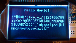
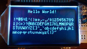
Standard ASCII table and traditional ‘Hello World!’:)

Ending slowly it’s time to tell something about fonts. As I said it is possible to simply write characters on the screen. To understand how all that thing works you need to know how the pixels are transfered to the display. The best explanation of the ST7565 display’s work can be in my opinion found here. TL;DR: the whole pixel space is divided into eight, 8-pixel high, horizontal pages divided into 128 columns that are 8 pixels high. If you didn’t understand, try link above. Nevertheless single letter is 8-pixel high and 5-pixel long so we need 5 bytes to store one letter. Its pixel map starts at left, top corner so it’s our (0,0) point and setting LSBof the first byte lights highest pixel. The font that is available in the code is Fixed 5×8 if someone is curious, it’s one of the default fonts in Xorg. To speed up conversion of the font to the display’s format I made simple OpenGL program to do the job for me. The code is of course available to download (check out my github).

DLs

Traditionally, at last some downloads:

  • First, and most important: C code of my program
  • ST7565 documentation can be found here

Posted in TutorialsTagged electronics, English, hardware, LCD, Linux, Raspberry Pi1 Comment

[Import]Using GNU Radio Companion – simple FM radio tutorial

Posted on September 4, 2017 - September 6, 2017 by Kamil (aka. v3l0c1r4pt0r)

NOTE: This post was imported from my previous blog – v3l0c1r4pt0r.tk. It was originally published on 1st November 2013.

This post is the second part of the Instructable mentioned on the previous post. That’s tutorial on how to make simple FM radio using GRC. That task is in my opinion the simplest project that can be made using GRC so it’s in fact beginners guide to GNU Radio which is really capable software. I hope that it is only the first my project using that software.

It isn’t hard to find GRC projects that implements FM radio functionality, that’s a fact. But when it comes to reproduce them so they are working just like SDR# you’d realize it’s a bit harder task. At least I did. I found about a three such projects but there was never any included project file and the only materials was video or pictures. I admit the video has pretty good explanation but it still wasn’t enough. The rest was even worse. They were only blog posts with few screen shots and short description. So finally to reproduce functionality of SDR#’s FM radio I had to think on my own. And after few hours I did what I tried to do.

A bit of theory

RTL-SDR Source Properties

But let’s start at the beginning. The first thing that you need to do to start creating your own FM receiver using GRC is to find FM station that can be received without disruptions so you can check if your program works as well as i.e. SDR#. It can be done with help of SDR# and when you found one you are ready to learn some theory about FM signal processing. In fact it could be omitted, but in my opinion it is better to know a bit. I personally am not any specialist in radio theory so it will be really simple and I might be wrong somewhere so if you find any mistake in that what I will write here just let me know in comments.

The simplest FM radio consists of few elements:

  • signal source – in our case it would be RTL-SDR dongle
  • low pass filter
  • WBFM demodulator
  • audio output – your PC’s sound card

There can be few other elements depending on input and output sample rate, if it will be possible to match them using only above elements there won’t be any other. So our task will be getting signal using RTL-SDR, passing it through low pass filter and FM demodulator and outputting on PC’s sound card. Meanwhile we will also need to match the sample rate of the input to the one of the output (2 MHz in to 48 KHz out). All elements of this circuit can be found by writing part of its name while list on the right is selected. Element’s names are the ones used as section header below.

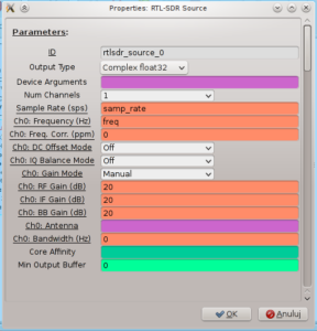
RTL-SDR source

Low Pass Filter Properties

Our signal input. We need to set its sample rate to 2M. It can be done by editing samp_rate variable and setting its value to 2e6. We need also to set the frequency of the station we want to receive. It is good practice to add every value that might be changed in the future as standalone variable. This can be done by adding Variable block from Variables category or, if you want to have possibility to edit it during the runtime block named WX GUI Slider or WX GUI Text Box and then just writing variable name as value in block’s properties.

Rational Resampler

Now we need to convert sample rate from 2M (samp_rate) to 500K which I realized is the best value for low pass filter’s input rate. To do that we need to add another variable, named i.e. quadrature, set its value to 500e3 (means: 500K). With that we need to add rational resampler’s block and set its decimation value to int(samp_rate/quadrature). Of course its input on the schematic should be connected to output of RTL-SDR Source (can be achieved by clicking on blue out on one block and then blue in on another).

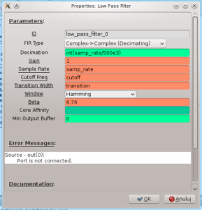
Low Pass Filter

The next step is to filter out frequencies other than the one we centered in th previous step. In that task we will use a low pass filter block. We here set cutoff frequency to 100e3. This is because that’s standard band’s width. I don’t know what correct value for transition width should be, but trying to change that I found that the higher value the better so it’s finally set to 1M. Obviously it should be connected to resampler’s output.

WBFM Receive

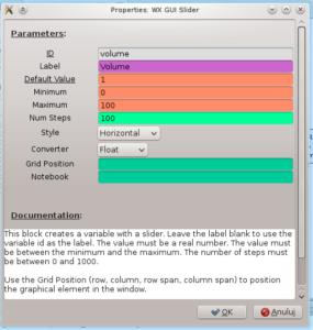
Volume slider Properties

Now we could do the nearly final and the most important step: placing the FM demodulator. In my case its quadrature rate equals 500k (that’s the same value as before so I set this to the value of quadrature variable). I don’t know if it could be changed to something else so if you are not sure just leave it as is. In that setting it should work.

Next Rational Resampler and Multiply Const

These elements’ job is to match the signal’s rate to the one supported by sound card and provide volume regulation. At first we need to convert rate from 500k to 48k so we need to decimate by 500 and then multiply by 48. In the second block we set const to volume. Now we can create variable or place WX GUI Slider with variable name set to volume. As you can see here color of WBFM demodulator is different than rational resampler’s and multiplier’s in and out. To change that you need to select them and use up and down arrows on your keyboard.

Audio Sink

That one’s function is to output signal on our sound card. Now its only required to edit its rate and choose 48k from a drop down list and that’s it! If you don’t have that option just choose the biggest value and edit value in rational resampler and it should work. Now you should be able to execute your program and test if it works. To hear anything it will probably be required to increase volume to about 50.

Finally: some links

If you don’t know how some part has been done or what value should have a particular variable below you can download projects that I’ve made first learning to use GRC myself and then preparing this tutorial. There is one project presented here and one made earlier.

Finished FM radio schematic

Posted in TutorialsTagged English, FM, GNU Radio, GRC, hardware, Linux, radio, RTL-SDR, SDR14 Comments

[Import]RTL-SDR under Arch Linux – getting started

Posted on September 4, 2017 - September 5, 2017 by Kamil (aka. v3l0c1r4pt0r)

NOTE: This post was imported from my previous blog – v3l0c1r4pt0r.tk. It was originally published on 1st November 2013.

First post about hardware was to be something different. Unfortunately it looks like that project already failed so it probably will never be published. Instead I’m starting, I hope series of posts, about cheap Software Defined Radio dongles based on RTL28xxU chips. This post will be short introduction to the topic of RTL-SDR and it will mostly be the same as my Instructable here.

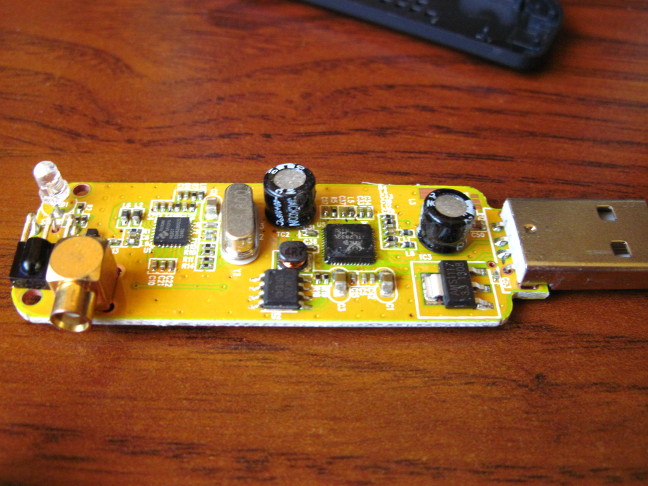
If you get here I imply that you already know what SDR is. If you don’t take a look at Instructable linked above. Getting one is for yourself should be easy. There are lots of offers on ebay that have names of chips included in the title so you should just search for rtl-sdr and i.e. R820T. That chip is one of the most capable and cheap in contrast to E4000.

Installation

The only things we will need here is some Linux distro and of course a tuner. As Linux I recommend Arch, because of availability of packages required and simplicity of its installation. There would be good if you have better antenna for the tuner and in that case you should also have adapter to standard antenna connector.

If you are ready you can now connect your dongle to PC and check using dmesg | tail or journalctl if it is has been detected by your system and if it contains appropriate chips.

If you chose the one with R820T it is probably required to disable default dvb_usb_rtl28xxu drivers, because, at least in my case, after disconnecting the dongle system hangs and the reason is for sure fault of that particular driver. You can disable it by creating new .conf file in /etc/modprobe.d directory. It could be done i.e. by typing # nano /etc/modprobe.d/blacklist.conf in console. The file should contain one line: blacklist dvb_usb_rtl28xxu. You also need to add that file to FILES variable in /etc/mkinitcpio.conf so it looks like that:FILES=”/etc/modprobe.d/blacklist.conf” and generate new initrd file by using # mkinitcpio -p linux. Now after restarting your computer everything should be OK.

Now we will need to install few packages to make RTL-SDR up and running. rtl-sdr and sdrsharp-svn are needed for basic functionality. You probably also want to install gnuradio and gr-osmosdr-git to make more advanced things like analysis of digital signal transmitted at 433 MHz. rtl-sdr is the main driver and can be installed on Arch from community repo:

# pacman -S rtl-sdr
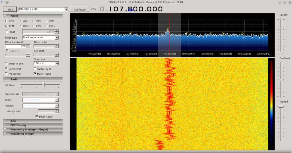
SDR# receiving FM station

There is also its git version available on AUR as rtl-sdr-git. SDR# is the program that offers basic capability to decode FM and AM radio and have easy to learn GUI so using it is the best for beginners. It is available on AUR as sdrsharp-svn.

The most capable software for RTL-SDR is GNU Radio and its graphical tool: GNU Radio Companion. It is also available on AUR (name: gnuradio). It is also required to install package gr-osmosdr-git from AUR in order to use RTL-SDR dongle as source in GRC. Its usage tutorial is available in the next post and as continuation of Instructable mentioned at the beginning of this post.

Now if you already installed all the required software you can try to find a radio station at about 100 MHz to check if everything is working fine. As mentioned earlier you could be able to listen to only the strongest stations on the default antenna. Finding one good signal will be useful in the next tutorial. At the end I’m enclosing screenshot of SDR# with settings proper to receive FM station.

Posted in TutorialsTagged English, hardware, Linux, radio, RTL-SDR, SDR1 Comment

[Import][Android] Odblokowywanie kanałów 12, 13, 14

Posted on September 4, 2017 - September 4, 2017 by Kamil (aka. v3l0c1r4pt0r)

NOTE: This post was imported from my previous blog – v3l0c1r4pt0r.tk. It was originally published on 18th June 2012.

Jak wspomniałem w swoim pierwszym wpisie dotyczącym Androida na tym systemie niemożliwe jest połączenie się z siecią działającą na kanale wyższym niż 11 (a więc takim, który jest zabroniony w USA). Ja jednak nie mieszkam w Stanach i chciałbym, aby mój telefon miał dostęp przynajmniej do tego co nie jest w Polsce nielegalne. Na szczęście udało mi się znaleźć rozwiązanie tego problemu.

Użycie tej metody wymaga dostępu do roota, więc jeśli twój telefon nie został jeszcze zrootowany odsyłam do strony Zeely’ego. Kolejnym wymaganiem będzie zainstalowanie do folderu bin sqlite’a (nie wiedzieć czemu ten, który można używać prze adb przestaje działać gdy wpiszemy w konsoli su). Potrzebne też będzie SDK Adroida (będę używał go, aby przeklejać komendy do konsoli, nada się też każdy emulator terminala np. Terminal IDE, ale tu trzeba będzie wszystko pisać ręcznie). Radzę też żeby koniecznie wykonać backup systemu z użyciem CWM (mnie przy pierwszej próbie coś poszło nie tak i musiałem przywracać kopię z poprzedniego dnia).

  1. Podłączamy telefon do komputera w trybie debugowania USB. Wchodzimy w Ustawienia=>Aplikacje i zaznaczamy Debugowanie USB.
  2. Potem należy uruchomić konsolę Windowsa (lub terminal gdy używamy Linuksa) i przejść do folderu, w którym zainstalowaliśmy SDK. Wpisujemy adb shell. Gdy wszystko pójdzie dobrze powinniśmy być już w konsoli naszego telefonu (pojawi się znak $). Można teraz wpisać su, aby uzyskać uprawnienia roota (# oznacza sukces).
  3. Aby móc zmodyfikować folder /system należy zamontować go do zapisu. Używamy komendy mount, aby odnaleźć odpowiednie urządzenie:
    $ mount
    mount
    rootfs / rootfs ro,relatime 0 0
    tmpfs /dev tmpfs rw,relatime,mode=755 0 0
    devpts /dev/pts devpts rw,relatime,mode=600 0 0
    proc /proc proc rw,relatime 0 0
    sysfs /sys sysfs rw,relatime 0 0
    tmpfs /mnt/asec tmpfs rw,relatime,mode=755,gid=1000 0 0
    tmpfs /mnt/obb tmpfs rw,relatime,mode=755,gid=1000 0 0
    /dev/block/mtdblock0 /system yaffs2 ro,relatime 0 0
    /dev/block/mtdblock3 /data yaffs2 rw,nosuid,nodev,relatime 0 0
    /dev/block/mtdblock2 /cache yaffs2 rw,nosuid,nodev,relatime 0 0
    /dev/block/mtdblock1 /data/idd yaffs2 rw,nosuid,nodev,relatime 0 0
    [...]
    $

    Właściwa linia została pogrubiona. Wpisujemy więc mount -o remount,rw -t rfs /dev/block/mtdblock0 /system (uwaga! Wartość po /dev/block/ może być inna).

  4. Teraz przenosimy plik sqlite3 (dostępny do pobrania na końcu wpisu) do folderu, w którym zainstalowane jest adb. Otwieramy w tym samym folderze drugie okno konsoli i wpisujemy w nie adb push sqlite3 /sdcard/ czym kopiujemy sqlite3 na kartę pamięci (tutaj ważne jest, żeby karta pamięci NIE była zamontowana w komputerze tj. w trybie MSC).
  5. Wracamy do poprzedniego okna, w którym wpisujemy cp /sdcard/sqlite3 /system/bin oraz chmod 4755 /system/bin/sqlite3.
  6. Na koniec montujemy system znów do odczytu: mount -o remount,ro -t rfs /dev/block/mtdblock0 /system.
  7. Teraz możemy wpisać sqlite3 i sprawdzić czy wszystko poszło pomyślnie. Jeśli tak przechodzimy do modyfikacji właściwego pliku.
  8. Zostajemy w tej samej konsoli (tą drugą można już zamknąć). Wpisujemy: sqlite3 /data/data/com.android.providers.settings/databases/settings.db “INSERT INTO secure (name, value) VALUES (‘wifi_country_code’, ‘JP’);”. Gdybyś nie chciał odblokowywać bądź co bądź zakazanego w Polsce kanału 14 możesz zmienić JP na EU w powyższej linii.
  9. Restartujemy telefon. Gdy system włączy się kanały 12,13 i 14 powinny już zostać odblokowane i powinno być już możliwe połączenie się z siecią na tych kanałach.

Nie jestem w stanie tego teraz sprawdzić, bo już zainstalowałem sqlite3 powyższą metodą, ale najpewniej, aby dokonać jego instalacji wystarczyłoby użyć jakiegokolwiek menadżera umożliwiającego modyfikację folderu /system. Potem wystarczyłoby tym samym programem zmienić chmody tak, aby możliwe byłoby wykonywanie pliku. Tym samym możnaby wtedy pominąć punkty 3-6.

Posted in TutorialsTagged Android, Gingerbread, kanał 14, polski, wifi, Xperia ProLeave a comment

[Import][Delphi] Wyświetlanie stanu za pomocą ProgresBar’a

Posted on September 4, 2017 - September 7, 2017 by Kamil (aka. v3l0c1r4pt0r)

NOTE: This post was imported from my previous blog – v3l0c1r4pt0r.tk. It was originally published on 19th April 2012.

Wydaje się, że jest to proste zadanie: wystarczy umieścić na formie kontrolkę, pozmieniać nieco style i gotowe. Niestety praktyka wygląda zupełnie inaczej. Każdy, kto chciał to osiągnąć w Windowsie Vista lub 7 pewnie wie, że nowe paski postępu jednym szczegółem uniemożliwiają wykonanie tego tak prosto. Dzieje się tak, ponieważ pasek postępu przy włączonym Aero jest animowany i w żaden udokumentowany sposób nie da się owej animacji wyłączyć.

Microsoft oczywiście zaleca, aby zamiast standardowego ProgressBar’a użyć coś, co nazywa ‘Meter’. I tu pojawia się kolejny problem, bo o tym rozwiązaniu wzmianka znajduje się jedynie w tym przewodniku, nie ma natomiast żadnego opisu, jak takie coś można osiągnąć w praktyce a jedynym programem, w którym można zobaczyć jak takie coś działa jest Eksplorator Windows. Niestety podejrzenie w jaki sposób jest to wykonane od strony kodu jest dla większości praktycznie niewykonalne (nie można podejrzeć styli kontrolki za pomocą programów takich jak WinDowse więc jedynym sposobem byłaby dekompilacja). Na szczęście jest jeden trick umożliwiający wykonanie kontrolki przypominającej microsoftowy meter. Jak w każdym obejściu problemu tak i tu jest niestety jeden haczyk: po zmianie skórki np. na Klasyczny Windows, bądź też przy próbie zastosowania go w starszych wersjach Windows nie zobaczymy nic. Wymusza to więc zastosowanie dwóch kontrolek: dla Windows Vista/7 – tej, którą zajmę się za chwilę oraz standardowego ProgressBar’a dla starszych Windowsów.

Sam kod nie jest ani trudny do użycia, ani też jego napisanie nie stanowiło większego problemu. Przedstawia się on następująco:

var:tRECT;
theme:HTHEME;
Progress:integer;
begin
  Progress:=50;
  theme := OpenThemeData(Handle,'PROGRESS');
  if theme<>0 then
  begin
    SetRect(r,0,0,25,100);
    DrawThemeBackground(theme,Form1.Canvas.Handle,11,2,r,nil);
    SetRect(r,0,Progress,25,100);
    DrawThemeBackground(theme,Form1.Canvas.Handle,6,4,r,nil);
    CloseThemeData(theme);
  end;
end;

Jak widać dwukrotnie została użyta funkcja DrawThemeBackground: pierwszy raz rysuje ona tło, za drugim razem została użyta do narysowania paska postępu, który w tym wypadku został ustawiony na połowie maksymalnej wartości, a ponieważ pasek ma wysokość równą 100 nie było konieczności stosowania żadnych dodatkowych funkcji do przeliczania tej wartości. Zamiast Form1.Canvas lepiej byłoby użyć komponentu TPaintBox, ewentualnie możnaby wtedy nieco zmodyfikować kod tak, aby wypełniał cały komponent co ułatwiłoby późniejsze modyfikacje. Kod należy wkleić do zdarzenia OnPaint używanego komponentu. Jeżeli powyższy przykład jest dla kogoś niejasny bądź nie wie do czego służą poszczególne argumenty odsyłam do opisów poszczególnych funkcji w bibliotece MSDN: OpenThemeData, SetRect, DrawThemeBackground oraz CloseThemeData. Do funkcji DrawThemeBackground można przekazać także inne wartości (parametry 3 i 4) używając wartości podanych tutaj.
Dla mnie jednak próbowanie wszyskich wartości nie było zbyt wygodne, napisałem więc prosty program umożliwiający szybkie przejrzenie wszyskich elementów, które można użyć. Program ten można ściągnąć stąd i nie zaliczam go do projektów, ponieważ nie zamierzam wprowadzać do niego żadnych poprawek.

Posted in TutorialsTagged Aero, Delphi, polski, WindowsLeave a comment

Posts navigation

Newer posts

Tags

Android assembly busybox C CAN can-hacking cc-factory cmake compiler docker Dreamspark electronics English gcc hacking hardware JavaCard JCOP kernel KiCAD library Linux PC PCB pinout PKI polski programming Python radio Raspberry Pi Reverse Engineering RTL-SDR SDC SDM SDR smart card software tor tty UART UEFi Windows X.509 Xperia Pro

Recent Posts

  • PHP build for use bundled in Android applications
  • Running graphical apps inside Docker containers
  • Plugin architecture demo for Python projects
  • Authorizing adb connections from Android command line (and making other service calls from cli)
  • How to recover torrent from rtorrent meta files

Recent Comments

  • pomi on Playing with GF-07 GPS device
  • pomi on Playing with GF-07 GPS device
  • Hamdy Abumgata on Playing with GF-07 GPS device
  • Mousum Gogoi on Playing with GF-07 GPS device
  • Eason on Sniffing USB traffic with DSLogic logic analyzer into pcap file

Categories

  • News
  • Random
  • Reversing LKV373A
  • Setting up new v3 Hidden Service with ultimate security
  • Tutorials
  • Uncategorized
  • Understanding JCOP

Links

  • Me @ github
  • LKV373A Wiki
  • DevTomek

Archives

  • December 2024
  • November 2024
  • May 2024
  • July 2023
  • October 2022
  • August 2022
  • July 2021
  • June 2021
  • May 2021
  • December 2020
  • November 2020
  • October 2020
  • August 2020
  • December 2019
  • November 2019
  • October 2019
  • August 2019
  • July 2019
  • February 2019
  • November 2018
  • October 2018
  • June 2018
  • May 2018
  • March 2018
  • February 2018
  • January 2018
  • December 2017
  • November 2017
  • September 2017

Meta

  • Log in
  • Entries feed
  • Comments feed
  • WordPress.org
Proudly powered by WordPress | Theme: micro, developed by DevriX.